Rotary baking device for wire and cable production

A technology of wire and cable and baking device, which is applied in drying, dryer, progressive dryer and other directions, can solve the problems of single wire and cable baking structure, insufficient and efficient baking, etc.

Active Publication Date: 2021-04-09
深圳市成天泰电缆实业发展有限公司
View PDF7 Cites 0 Cited by
  • Summary
  • Abstract
  • Description
  • Claims
  • Application Information

AI Technical Summary

Problems solved by technology

[0003] The baking device for wire and cable production disclosed in the prior art has a single structure for baking wire and cable, and the baking is not thorough enough and efficient, and has relatively large limitations.

Method used


Image

  • Rotary baking device for wire and cable production
  • Rotary baking device for wire and cable production
  • Rotary baking device for wire and cable production

Examples


Embodiment 1

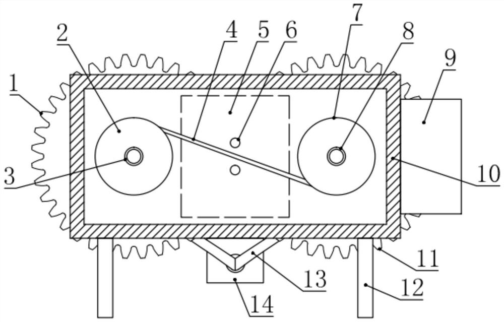
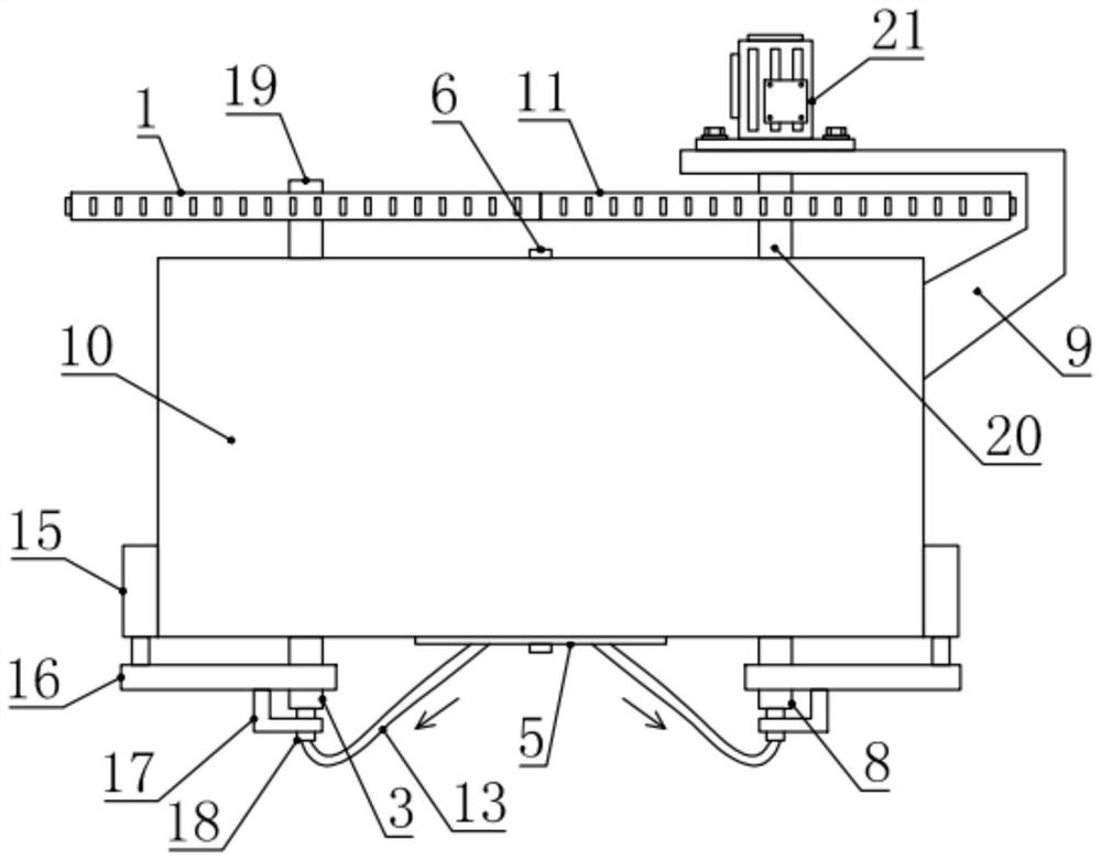
[0023] see Figure 1-3 , in an embodiment of the present invention, a rotary baking device for wire and cable production, including a baking oven body 10, a supporting leg 12 is installed on the bottom of the baking oven body 10, and the supporting leg 12 can be opposite to the baking oven body. 10 for support, the left and right sides of the inside of the oven body 10 are respectively provided with a first winding assembly 2 and a second winding assembly 7, and the rear of the first winding assembly 2 and the second winding assembly 7 A post 25 is installed and fixed at the two ends respectively, and the first rotary tube 19 and the second rotary tube 20 are respectively matched and slidably connected on the two post 25, and the first rotary tube 19 and the second rotary tube 20 are connected with the oven body 10. The rear side wall is rotatably connected, and a drive mechanism for driving the first rotating tube 19 and the second rotating tube 20 to rotate in reverse is ins...

Embodiment 2

[0027] see Figure 1-4 , the difference between this embodiment and embodiment 1 is:

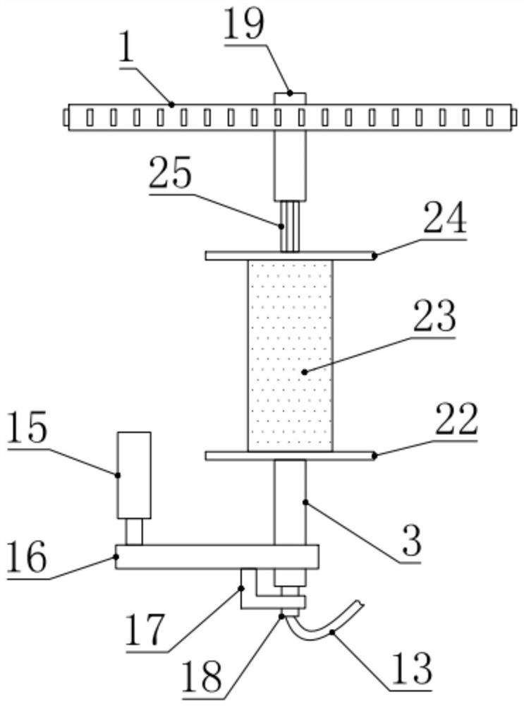
[0028] In this embodiment, the structures of the first winding assembly 2 and the second winding assembly 7 are the same, and both the first winding assembly 2 and the second winding assembly 7 include a front baffle 22 and a winding cylinder 23 And rear baffle plate 24, described coiling net cylinder 23 is cylindrical reticular tube body, front and rear baffle plate 22 and rear baffle plate 24 are installed and fixed respectively at the front and rear ends of coiling net cylinder 23, through coiling net cylinder 23 The setting is conducive to the discharge of hot air, thereby improving the baking effect of the wire and cable 4.

[0029] The first rotating tube 19 and the second rotating tube 20 are horizontally and parallelly arranged, and one end of the post 25 is fixed at the middle position of the tailgate 24, and the cross section of the post 25 is a regular polygon, which facilitates ...


PUM


Abstract

The invention relates to the field of electric wire and cable baking, in particular to a rotary baking device for wire and cable production. The device comprises a baking box body, a first winding assembly and a second winding assembly are respectively arranged at the left side and the right side in the baking box body, and an inserting column is fixedly arranged at the rear end of each of the first winding assembly and the second winding assembly; a first rotating pipe and a second rotating pipe are slidably connected to the two inserting columns in a matched manner correspondingly, a driving mechanism used for driving the first rotating pipe and the second rotating pipe to rotate reversely is further installed at the outer side of the baking box body, and a first supporting pipe and a second supporting pipe are fixedly installed at the front end of the first winding assembly and the front end of the second winding assembly correspondingly; and linkage frames are rotationally installed on the first supporting pipe and the second supporting pipe at the outer side of the baking box body, telescopic cylinders are further fixedly installed on the linkage frames, and the front end of the first supporting pipe and the front end of the second supporting pipe are further connected with temperature control fans installed at the outer side of the baking box body through air conveying assemblies correspondingly. The baking structure of the device is novel, and baking is thorough and efficient.

Description

technical field [0001] The invention relates to the field of wire and cable baking, in particular to a rotary baking device for wire and cable production. Background technique [0002] Wires and cables are widely used in all walks of life. Wires generally consist of two parts. The plastic insulating sheath wraps the copper or aluminum core inside, and the outer sheath is to prevent the inner core from being mechanically damaged. Wires and cables are made by three processes: drawing, twisting, and coating. The coating is mainly to cover the molten plastic on the copper or aluminum core to form a plastic insulation layer, and then through cooling The water cools the plastic insulation layer, so that water droplets will remain on the surface of the cooled plastic insulation layer, and these water droplets need to be dried. [0003] The baking device for wire and cable production disclosed in the prior art has a single structure for baking wire and cable, and the baking is not ...

Claims


Application Information

Patent Timeline
Patent Type & Authority Applications(China)
IPC IPC(8): F26B13/04F26B21/10F26B25/02
CPCF26B13/003F26B21/001F26B21/004F26B21/10F26B25/02
Inventor 尹灵邓旺杨英合彭茂华刘小怀
Owner 深圳市成天泰电缆实业发展有限公司
Why Eureka
Try Eureka