Optical lens and imaging equipment

A technology of optical lens and imaging surface, applied in the field of imaging lens, can solve the problems of not combining super large aperture, etc., to achieve the effect of improving camera experience and increasing shutter speed

Active Publication Date: 2021-05-25
JIANGXI LIANYI OPTICS CO LTD
View PDF5 Cites 0 Cited by
  • Summary
  • Abstract
  • Description
  • Claims
  • Application Information

AI Technical Summary

Problems solved by technology

In recent years, with the enthusiasm of consumers for taking pictures with mobile phones, nighttime live photography has become a trend in life, which requires mobile phones to have the same effect as during the day when taking pictures at night. For the lens, it means a large aperture, and There is currently no lens on the market that combines super wide aperture and ultra high definition

Method used


Image

  • Optical lens and imaging equipment
  • Optical lens and imaging equipment
  • Optical lens and imaging equipment

Examples


no. 1 example

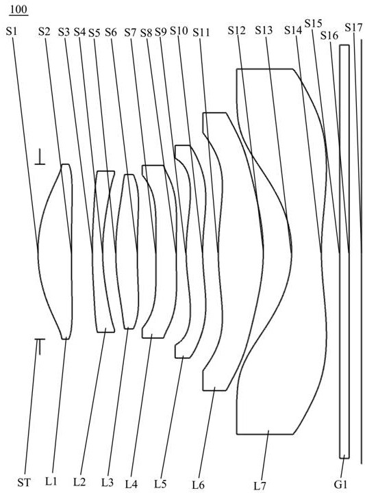
[0066] see figure 1 , which is a schematic structural view of the optical lens 100 provided in the first embodiment of the present invention, the optical lens 100 includes in sequence from the object side to the imaging surface along the optical axis: a stop ST, a first lens L1, a second lens L2, a second lens L2, Three lenses L3, fourth lens L4, fifth lens L5, sixth lens L6, seventh lens L7 and infrared filter G1.

[0067] The first lens L1 has positive refractive power, the object side S1 of the first lens is a convex surface, and the image side S2 of the first lens is a concave surface at the near optical axis;

[0068] The second lens L2 has a negative refractive power, the object side S3 of the second lens is a convex surface, and the image side S4 of the second lens is a concave surface;

[0069] The third lens L3 has positive refractive power, the object side S5 of the third lens is a convex surface, and the image side S6 of the third lens is a concave surface;

[007...

no. 2 example

[0086] For the structural schematic diagram of the optical lens 200 provided in this embodiment, please refer to Figure 5 , the structure of the optical lens 200 in this embodiment is substantially the same as that of the optical lens 100 in the first embodiment, except that the radius of curvature and material selection of each lens are different.

[0087] The relevant parameters of each lens in the optical lens 200 provided in this embodiment are shown in Table 3.

[0088] table 3

[0089]

[0090] The surface coefficients of each aspheric surface of the optical lens 200 in this embodiment are shown in Table 4.

[0091] Table 4

[0092]

[0093] In this embodiment, the graphs of field curvature, vertical chromatic aberration and axial chromatic aberration of the optical lens 200 are shown as Image 6 , Figure 7 with Figure 8 shown by Figure 6 to Figure 8 It can be seen that both field curvature and chromatic aberration of the optical lens 200 are well correct...

no. 3 example

[0098] see Figure 9 , which is a schematic structural view of the optical lens 300 provided in this embodiment, the structure of the optical lens 300 in this embodiment is roughly the same as that of the optical lens 100 in the first embodiment, the difference is that the radius of curvature of each lens and material choices vary.

[0099] The relevant parameters of each lens in the optical lens 300 provided in this embodiment are shown in Table 5.

[0100] table 5

[0101]

[0102] Table 6 shows the surface coefficients of each aspheric surface of the optical lens 300 in this embodiment.

[0103] Table 6

[0104]

[0105] In this embodiment, the graphs of field curvature, vertical chromatic aberration and axial chromatic aberration of the optical lens 300 are shown as Figure 10 , Figure 11 with Figure 12shown by Figure 10 to Figure 12 It can be seen that the field curvature, distortion and chromatic aberration of the optical lens 300 are well corrected.

[...


PUM


Abstract

The invention discloses an optical lens and an imaging device. The optical lens comprises: an aperture from the object side to the imaging surface along the optical axis; is concave at the center; the second lens with negative power has a convex object side and concave image side; the third lens with positive power has a convex object side and concave image side; it has negative power The fourth lens, its object side is concave, the image side is concave at the near optical axis; the fifth lens with positive refractive power, its object side is convex at the near optical axis, and its image side is at the near optical axis Concave surface; the sixth lens with positive refractive power, its object side is convex at the near optical axis, and its image side is convex; the seventh lens with negative refractive power, its object side is concave at the near optical axis, its The image side is concave at the near optical axis and has at least one point of inflection. The optical lens has the advantages of large aperture and ultra-high-definition imaging.

Description

technical field [0001] The invention relates to the technical field of imaging lenses, in particular to an optical lens and imaging equipment. Background technique [0002] At present, with the popularization of portable electronic devices (such as smartphones, tablets, and cameras), coupled with the popularity of social, video, and live broadcast software, people are more and more fond of photography, and camera lenses have become a must for electronic devices. Standard configuration, camera lenses have even become the primary consideration for consumers when purchasing electronic equipment. [0003] With the continuous development of mobile information technology, portable electronic devices such as mobile phones are also developing in the direction of large aperture and ultra-high-definition imaging, which puts forward higher requirements for camera lenses mounted on portable electronic devices. In recent years, with the enthusiasm of consumers for taking pictures with m...

Claims


Application Information

Patent Timeline
Patent Type & Authority Patents(China)
IPC IPC(8): G02B13/00G02B13/18
CPCG02B13/0045
Inventor 王义龙刘绪明曾昊杰曾吉勇
Owner JIANGXI LIANYI OPTICS CO LTD
Why Eureka
Try Eureka