Eureka AIR delivers breakthrough ideas for toughest innovation challenges, trusted by R&D personnel around the world.

Channel device and transmission method

A channel device and channel technology, which is applied to the device for accepting coins, handling coins or valuable banknotes, instruments, etc., can solve the problems of poor operation stability of the three-way commutator, uneven transmission channel path, and high failure rate of equipment. Achieve the effect of improving transmission stability, smooth transmission path, and reasonable transmission path

Pending Publication Date: 2021-04-09
SHENZHEN YIHUA COMP +2
View PDF0 Cites 0 Cited by
  • Summary
  • Abstract
  • Description
  • Claims
  • Application Information

AI Technical Summary

Problems solved by technology

[0003] There are many module structures in the self-service terminal, and the O-shaped transmission part causes the path of the transmission channel to be uneven, so the medium needs to pass through the three-way commutator several times during the transmission process to assist in changing the direction, and the operation of the three-way commutator Poor stability, leading to high failure rate of equipment

Method used


Image

  • Channel device and transmission method
  • Channel device and transmission method
  • Channel device and transmission method

Examples


specific Embodiment approach

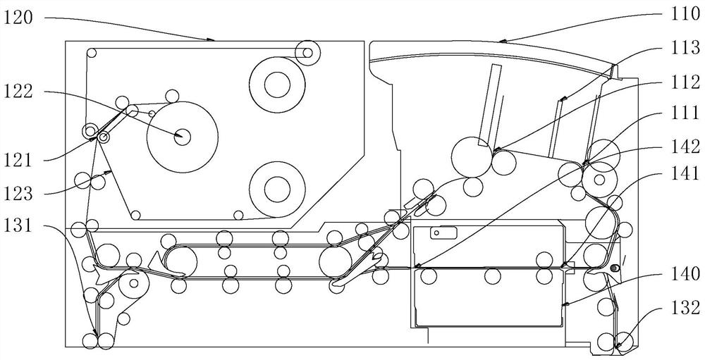
[0040] Please refer to the attached figure 1 , as a specific embodiment of the present invention, a self-service terminal, including a casing and a passenger receiving module 110, a first receiving module 120 and a transmission channel arranged inside the casing, and the transmission channel allows the medium 100 to pass through the passenger receiving module 110, transmission between the first receiving module 120.

[0041] In addition, a second receiving module may optionally be provided for storing or extracting the medium, and correspondingly, the first receiving module 110 plays a role of temporarily storing the medium.

[0042] Optionally, the receiving module 110 and the first receiving module 120 are arranged in the upper movement, and the second receiving module is arranged under the upper movement. The passenger receiving module 110 is arranged at the front end of the turning center 156 , and the first receiving module 120 is arranged at the rear end of the turning ...

specific Embodiment

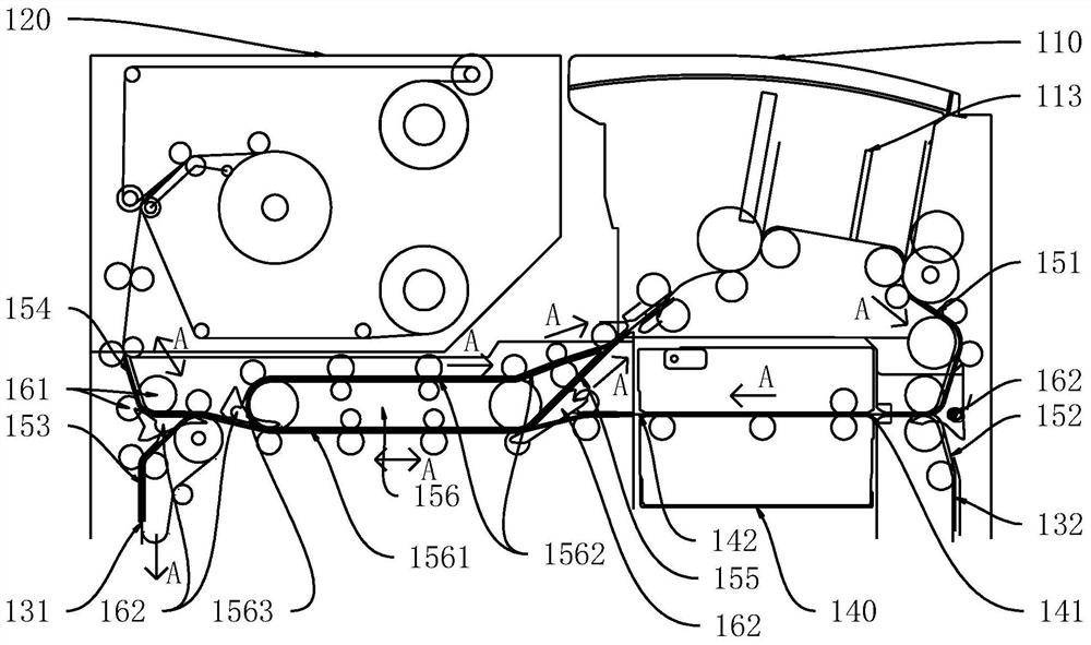
[0072] Please refer to the attached figure 2 , as a specific embodiment provided by the present invention, a medium storage method applied to the aforementioned self-service terminal, the medium 100 moves along the direction indicated by the arrow A in the figure, and the steps are as follows:

[0073] The user puts the medium 100 into the input space of the receiving module 110. After the transmission component is started, the medium 100 enters the first channel 151 from the medium inlet 111, and the medium 100 enters the inspection module 140 along with the first channel 151 for inspection and obtains the inspection result;

[0074] The inspection results are divided into two types: qualified and unqualified. The qualified medium 100 is output from the output terminal 142 of the inspection module 140 and then transported to the first entrance and exit 121 along the first channel 151, the first transfer channel 1561, and the fourth channel 154. , the qualified medium 100 is ...


PUM


Abstract

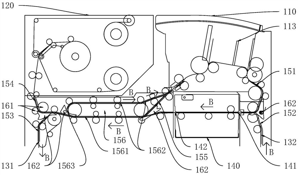
The embodiment of the invention discloses a channel device and a transmission method. The channel device comprises a receiving module, a first receiving module and a transmission channel, wherein a medium is transmitted in the transmission channel, the transmission channel comprises a rotation center, the rotation center comprises a first transfer channel, a second transfer channel and a third transfer channel, the second transfer channel is arranged above the first transfer channel, and a medium inlet is communicated with the front end of the first transfer channel; the first passageway is communicated with the rear end of the first transfer channel, and the two ends of the first transfer channel are communicated with the medium outlet through the second transfer channel and the third transfer channel respectively; the medium can be output from the medium outlet through the second transfer channel and can also be output from the medium outlet through the third transfer channel. The medium passes through the rotation center when being transmitted in the transmission channel, wherein the rotation center enables a transmission path of the medium to be smooth and uneasy to block.

Description

technical field [0001] The invention relates to the technical field of self-service terminals, in particular to a channel device and a transmission method. Background technique [0002] The self-service terminal makes people's life more convenient. In the existing self-service terminal, the transmission path switching of the medium between each functional module is realized through the joint operation of the O-shaped transmission part and the three-way commutator: the commutator is used to limit The path of medium transmission, the O-shaped transmission part is used to change the transmission direction of the medium. [0003] There are many module structures in the self-service terminal, and the O-shaped transmission part causes the path of the transmission channel to be uneven, so the medium needs to pass through the three-way commutator several times during the transmission process to assist in changing the direction, and the operation of the three-way commutator The stab...

Claims


Application Information

Patent Timeline
IPC IPC(8): G07D11/18G07D11/14
CPCG07D11/14G07D11/18
Inventor 高海源
Owner SHENZHEN YIHUA COMP
Why Eureka
Eureka Blog
Learn More