Display device and terminal equipment
A technology for display devices and display areas, which is applied to identification devices, static indicators, instruments, etc., and can solve problems such as poor assembly, poor compression resistance, and poor flatness of the display screen
- Summary
- Abstract
- Description
- Claims
- Application Information
AI Technical Summary
Problems solved by technology
Method used
Image
Examples
Embodiment 1
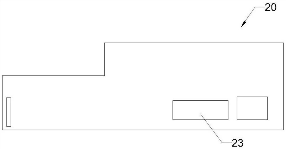
[0031] An embodiment of the present invention provides a display device 100, such as image 3 As shown, the display device 100 includes a middle frame 30 , a flexible circuit board 20 and a display panel 10 . The display panel 10 has a display surface and a non-display surface opposite to the display surface, and the middle frame 30 is disposed on the non-display surface of the display panel 10 .
[0032] Such as Figure 4 As shown, the display panel 10 has a display area 11 and a non-display area 12 surrounding the display area 11. In the non-display area 12, the display panel 10 has a binding area 13, the binding The fixed area 13 is electrically connected to the connecting end of the flexible circuit board 20 . The display panel 10 displays image frames according to the signals transmitted from the components 23 on the flexible circuit board 20 .
[0033] Such as Figure 5 As mentioned above, the flexible circuit board 20 is located on one side of the binding area 13 of...
Embodiment 2
[0041] An embodiment of the present invention provides a display device 100', such as Figure 6 As shown, the display device 100' includes a middle frame 30', a flexible circuit board 20' and a display panel 10. The display panel 10 has a display surface and a non-display surface opposite to the display surface, and the middle frame 30' is disposed on the non-display surface of the display panel 10.
[0042] Such as Figure 4 As shown, the display panel 10 has a display area 11 and a non-display area 12 surrounding the display area 11. In the non-display area 12, the display panel 10 has a binding area 13, the binding The fixed area 13 is electrically connected to the connecting end of the flexible circuit board 20'. The display panel 10 displays images according to the signals transmitted from the components 23' on the flexible circuit board 20'.
[0043] Such as Figure 7 As mentioned above, the flexible circuit board 20' is located on one side of the binding area 13 of ...
Embodiment 3
[0052] An embodiment of the present invention provides a display device 100", such as Figure 8 As shown, the display device 100" includes a middle frame 30", a flexible circuit board 20" and a display panel 10. The display panel 10 has a display surface and a non-display surface opposite to the display surface, The middle frame 30 ″ is disposed on the non-display surface of the display panel 10 .
[0053] Such as Figure 4 As shown, the display panel 10 has a display area 11 and a non-display area 12 surrounding the display area 11. In the non-display area 12, the display panel 10 has a binding area 13, the binding The fixed area 13 is electrically connected to the connecting end of the flexible circuit board 20 ″. The display panel 10 displays image images according to the signals transmitted from the components 23 ″ on the flexible circuit board 20 ″.
[0054] Such as Figure 7 Said, the flexible circuit board 20" is located on one side of the binding area 13 of the disp...
PUM
 Abstract
Description
Claims
Application Information
 - R&D
- Intellectual Property
- Life Sciences
- Materials
- Tech Scout
- Unparalleled Data Quality
- Higher Quality Content
- 60% Fewer Hallucinations
Browse by: Latest US Patents, China's latest patents, Technical Efficacy Thesaurus, Application Domain, Technology Topic, Popular Technical Reports.
© 2025 PatSnap. All rights reserved.Legal|Privacy policy|Modern Slavery Act Transparency Statement|Sitemap|About US| Contact US: help@patsnap.com


