
Electronic control relay

A technology for controlling relays and relays, applied in chemical instruments and methods, relay bases/shells/covers, cleaning methods and appliances, etc., can solve the problem of inability to realize auxiliary elastic locking, easy accumulation of dust on the display screen, and inconvenient disassembly and assembly And other issues

Inactive Publication Date: 2021-04-09
张伟斌
View PDF1 Cites 0 Cited by
  • Summary
  • Abstract
  • Description
  • Claims
  • Application Information

AI Technical Summary

Problems solved by technology

[0007] In order to solve the above technical problems, the present invention provides an electronic control relay to solve the problem that the existing device is not convenient enough for disassembly and assembly, and it cannot realize the disassembly structure and locking structure and The organic combination with the protective structure; moreover, the existing device tends to accumulate dust on the display screen after being used for a period of time, and it cannot realize the automatic cleaning of the display screen during disassembly and assembly through structural improvement; finally, the existing The knob on the device is easily damaged after repeated adjustments, and it is impossible to achieve auxiliary elastic locking in case of urgent problems

Method used


Image

  • Electronic control relay
  • Electronic control relay
  • Electronic control relay

Examples


Embodiment Construction

[0029] Embodiments of the present invention will be further described in detail below in conjunction with the accompanying drawings and examples. The following examples are used to illustrate the present invention, but should not be used to limit the scope of the present invention.

[0030] as attached figure 1 to attach Figure 7 Shown:

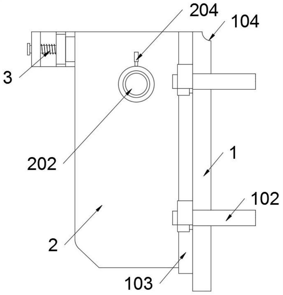
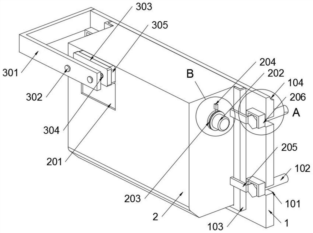
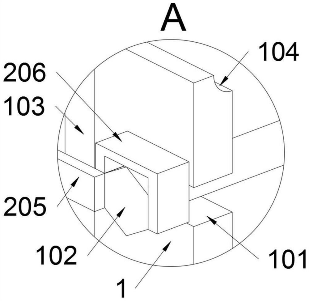
[0031] The present invention provides an electronic control relay, including a fixed seat 1; a relay main body 2 is installed on the fixed seat 1, and an auxiliary structure 3 is also installed on the fixed seat 1; refer to figure 2 and image 3 , the relay body 2 includes a limit block 205, two limit blocks 205 are welded to the left end of the relay body 2, and two limit blocks 205 are also welded to the right end of the relay body 2; the four limit blocks 205 are L-shaped structure, and when the relay main body 2 is clamped in the card seat 103, the limit block 205 is in contact with the head end of the fastening bolt 102, thereby re...


PUM


Abstract

The invention provides an electronic control relay, relates to the technical field of relays, and solves the problems that: organic combination of a disassembly and assembly structure, a locking structure and a protection structure cannot be realized through structural improvement; automatic cleaning of a display screen cannot be realized during disassembly and assembly through the structural improvement; and auxiliary elastic locking cannot be realized for emergency. The electronic control relay comprises a fixed seat; a relay main body is installed on the fixed seat, and an auxiliary structure is further installed on the fixed seat. The seat body is of a concave structure and is matched with the head end of a fastening bolt; when the relay main body is clamped in a clamping seat, the seat body and the head end of the fastening bolt are in a clamping state, and the seat body forms a protection structure of the head end of the fastening bolt, so that collision protection of the head part of the fastening bolt can be realized.

Description

technical field [0001] The invention belongs to the technical field of relays, and more specifically relates to an electronic control relay. Background technique [0002] The relay is an electrical control device, which is an electrical appliance that causes the controlled quantity to undergo a predetermined step change in the electrical output circuit when the change of the input quantity meets the specified requirements. [0003] For example, the application number: CN201010107535.0, the present invention relates to an electronic control relay, on the panel facing towards the housing side and extending straight back to form several fixed sides, each fixed side is provided with a card slot along its extending direction, There are several positioning slots on the card slot on the fixed side of the corresponding panel on the side of the base facing the shell; the four circuit boards of the power supply board, the power supply connection board, the setting board and the front ...

Claims


Application Information

Patent Timeline
IPC IPC(8): H01H45/02B08B1/00
CPCH01H45/02B08B1/143
Inventor 张伟斌
Owner 张伟斌
Learn More