Arc extinguishing structure of direct-current contactor

A DC contactor and arc extinguishing technology, which is applied in the direction of relays, electromagnetic relays, electromagnetic relay details, etc., can solve problems that affect the electrical life of products, affect the purity of gas media, and are not resistant to arcs.

Pending Publication Date: 2021-04-09
上海为鹏科技有限公司
View PDF0 Cites 0 Cited by
  • Summary
  • Abstract
  • Description
  • Claims
  • Application Information

AI Technical Summary

Problems solved by technology

[0003] DC contactors generate arcs when breaking high-voltage and high-current circuits. Unlike AC currents, there is a zero-crossing point that facilitates arc extinguishment, so DC arcs are more difficult to extinguish. The temperature when the arc burns reaches several thousand degrees. The contacts and other components have great damage, affecting the electrical life of the product
Existing products usually use the magnetic blowing method of permanent magnets to extinguish the arc. The structural parts of the arc extinguishing chamber are made of ceramic materials or plastic materials. However, due to technological limitations, the ceramic parts cannot form a structure with arc extinguishing grids and surround the contacts. The arc extinguishing chamber made of plastic materials is not resistant to electric arcs and will produce other gas impurities after ablation, which will affect the purity of the gas medium in the arc extinguishing chamber. Therefore, the arc extinguishing chambers composed of two single materials have certain Defects affect the arc extinguishing performance of the DC contactor

Method used


Image

  • Arc extinguishing structure of direct-current contactor
  • Arc extinguishing structure of direct-current contactor
  • Arc extinguishing structure of direct-current contactor

Examples


Embodiment Construction

[0022] In order to make the purpose, technical solutions and advantages of the embodiments of the present invention more clear, the technical solutions in the embodiments of the present invention will be clearly and completely described below in conjunction with the drawings in the embodiments of the present invention.

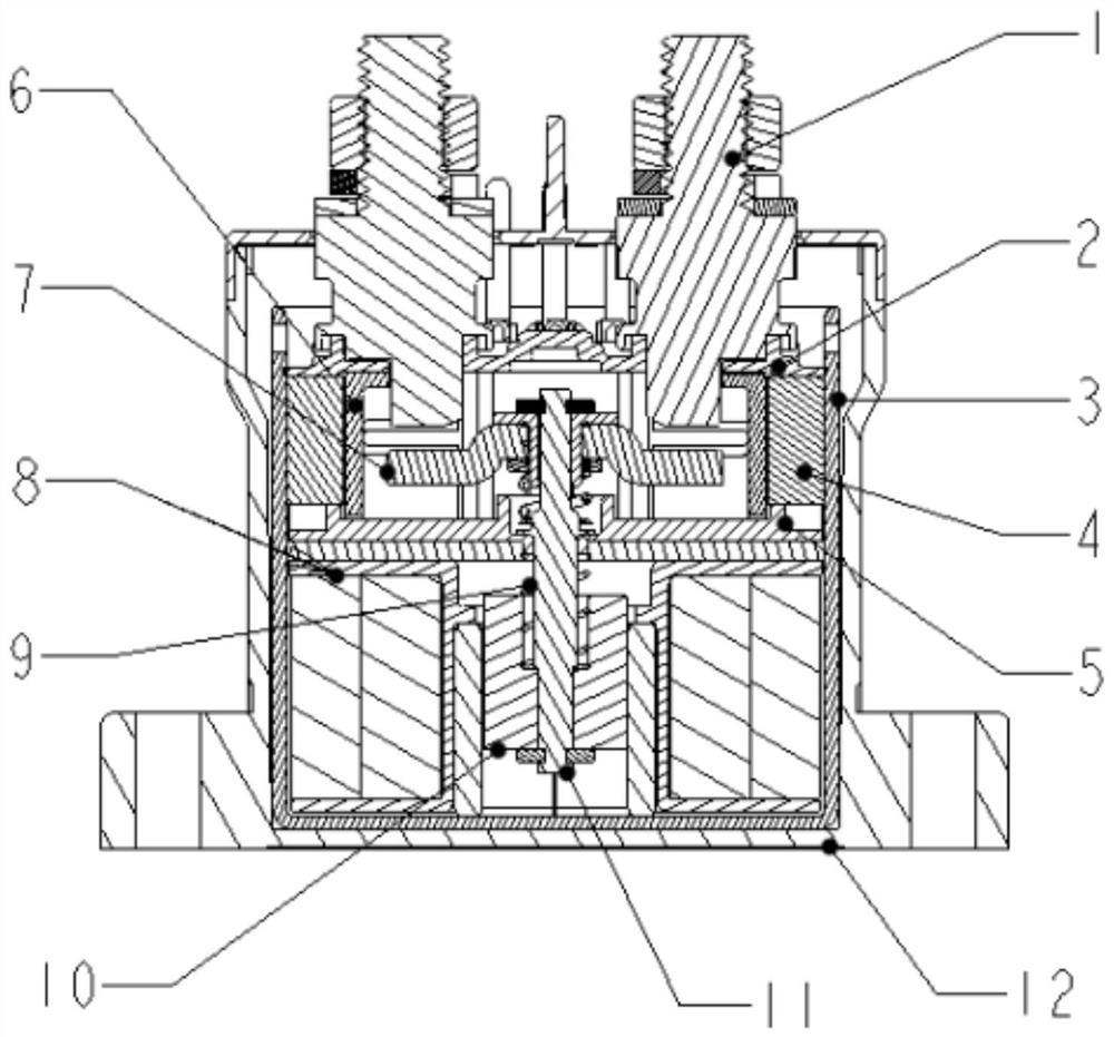
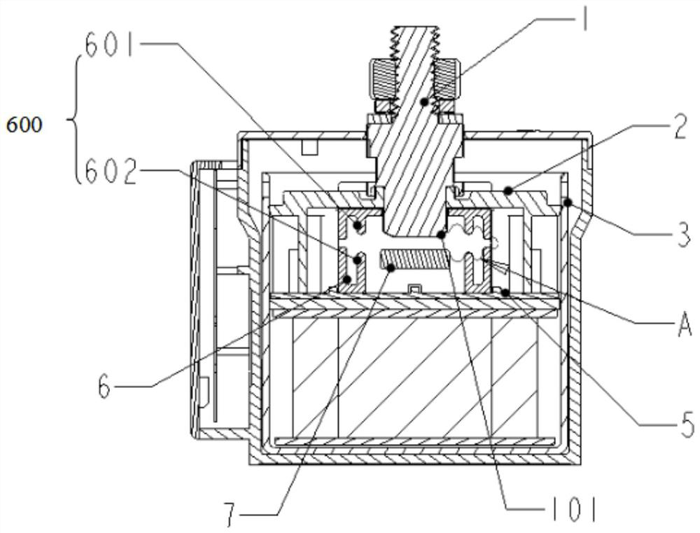
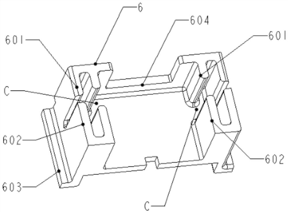
[0023] Such as Figure 1-Figure 4 As shown, the present invention discloses an arc extinguishing structure of a DC contactor, which includes an arc extinguishing cover 2, and a pair of static contacts 1 that pass through the arc extinguishing cover 2 and sit on it are provided with a static contact 1 Matching moving contact assembly 9. The static contact 1 is made of metal material and can be injection molded into one body or assembled together with the plastic-molded arc extinguishing cover 2 . The moving contact assembly 9 includes moving contacts 7, and each static contact 1 is in contact with or disconnected from a corresponding moving contact 7 to realiz...


PUM


Abstract

The invention discloses an arc extinguishing structure of a direct-current contactor. The structure comprises an arc extinguishing cover, moving contacts that make contact with or are separated from a pair of static contacts are arranged below the static contacts that penetrate through the arc extinguishing cover and are located above the arc extinguishing cover, the moving contacts and static contacts are contacted or separated to generate electric arcs and the outer side of each static contact is provided with a permanent magnet used for magnetic blow-out of the electric arc. The magnetic field directions of the permanent magnets are parallel to the direction of the center connecting line of the two static contacts, an arc extinguishing piece made of ceramic materials is arranged between each static contact and the corresponding permanent magnet on the outer side, and a side wall structure is arranged on each arc extinguishing piece and used for blocking at least part of electric arcs and / or increasing the crawling distance of the electric arcs. The side wall structure is provided with an opening through which an electric arc blows, and the opening is used for narrowing the electric arc. The area around the arc in the arc extinguishing chamber is made of the ceramic material, the arc extinguishing characteristic is increased, rapid arc extinguishing is facilitated, and the arc extinguishing performance of the direct current contactor is improved in combination with the magnetic blow-out characteristic of the permanent magnet to the arc.

Description

technical field [0001] The invention relates to the field of DC contactors, in particular to an arc extinguishing structure of a high-voltage and high-current DC contactor, which uses a strong magnetic blower and insulating components to extinguish the DC arc and improves the electrical life of the DC contactor. Background technique [0002] In recent years, with the development of new energy electric vehicles, charging piles and energy storage batteries, the application of high-voltage DC contactors has become more and more common, and has become an essential electrical component for controlling the on-off of DC circuits in electric vehicles and charging piles. DC contactors usually use an electromagnetic system composed of coils and iron cores as the control and execution components to drive the internal mechanism of the contactor to make the moving contacts and static contacts on or off to realize the switching function. [0003] DC contactors generate arcs when breaking ...

Claims


Application Information

Patent Timeline
IPC IPC(8): H01H50/54H01H9/44H01H9/34
CPCH01H9/34H01H9/443H01H50/54
Inventor 不公告发明人
Owner 上海为鹏科技有限公司
Why Eureka
Try Eureka