Electromagnetic railgun

An electromagnetic rail gun and guide rail technology, which is applied to electromagnetic launchers, weapons without explosives, offensive equipment, etc., can solve the problems that the service life is difficult to meet the requirements of practical applications, limit the service life of electromagnetic guns, and damage the guide rail and inner bore. , to achieve the effect of reducing ablation, suppressing electric contact arc, and suppressing harm

Inactive Publication Date: 2007-08-22
HUAZHONG UNIV OF SCI & TECH
View PDF0 Cites 11 Cited by
  • Summary
  • Abstract
  • Description
  • Claims
  • Application Information

AI Technical Summary

Problems solved by technology

Hybrid armatures have the potential to fire at rates comparable to or even higher than plasma armatures; allow selection of smaller armature lengths to reduce plasma ablation of structural materials such as rails; hybrid armature electrical efficiency is slightly higher than plasma body armature, but still far below the solid armature, and due to the ablation of the plasma brush, its service life is still difficult to meet the requirements of practical applications
[0008] In short, the plasma armature and the hybrid armature have a higher firing velocity than the solid armature, but the electrical efficiency is low, and the plasma arc seriously damages the guide rail and the inner bore, which greatly limits the service life of the electromagnetic gun
The solid armature can obtain a higher service life, but at the expense of the launch velocity

Method used


Image

  • Electromagnetic railgun
  • Electromagnetic railgun

Examples


Embodiment Construction

[0019] Hereinafter, the present invention will be further described in detail with reference to the accompanying drawings.

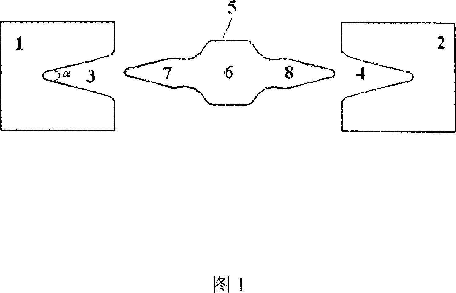
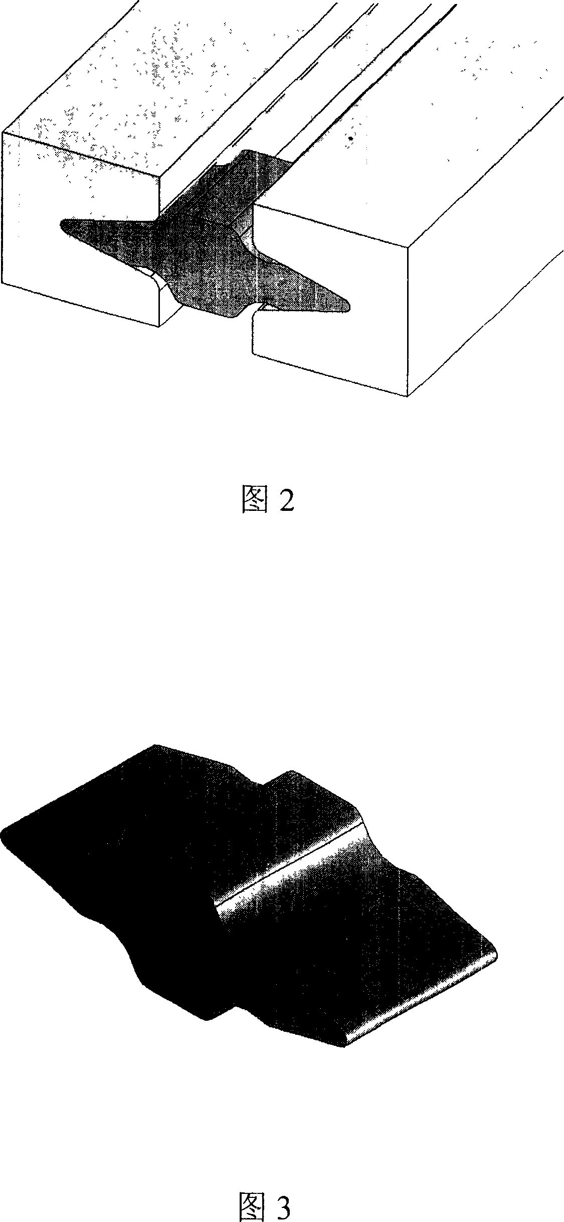
[0020] As shown in Figures 1 to 3, the structure of an electromagnetic railgun is that the first rail 1 and the second rail 2 are parallel, an insulating material is placed between the first rail 1 and the second rail 2, and an external support Structure, the first and second guide rails 2 are provided with a first V-shaped groove 3 and a second V-shaped groove 4 respectively. The depth of the first V-shaped groove 3 is similar to the caliber of the railgun, and its tail and opening All are rounded, the opening angle a of the first V-shaped groove 3 is 30-60 degrees, and the second V-shaped groove 4 is symmetrical with the first V-shaped groove 3;

[0021] A solid armature 5 is placed between the first rail 1 and the second rail 2. The structure of the solid armature 5 is that the first side wing 7 and the second side wing 8 extend from the main body 6 to bo...


PUM


Abstract

The invention discloses an electromagnetism rail gun which the structure is: the insulation material is between the first rail and second guide rail which are all opened with the symmetrical 'V' slot. The angle of the slot is 30-60degree. The solid armature is set between the first and second guide rail. The two symmetrical side wings extend to both sides from the body which the shape and size is matched to the 'V' slot. The upper and lower surface of the two side wing front contacts with the 'V' slot to form the electrical contact surface of the solid armature and the guide rail; the back end of the two side wings are separate with the two guide rail. The invention can control the damage of the transitional voltaic arc, so it can prolong the gun using life but getting the higher shooting speed (>3kms), so it has the widely future.

Description

Technical field [0001] The invention belongs to an electromagnetic launch weapon, and specifically relates to an electromagnetic railgun. Background technique [0002] The electromagnetic railgun is a new concept weapon, including two parallel rails. Between the two rails, a small object that maintains good electrical contact with the two rails and can slide along the rails is placed as a projectile. It can slide freely, and there is a diversion armature at the back of the projectile. [0003] In the development process of electromagnetic railgun technology, various armature structures have appeared. Generally speaking, they can be divided into three types: plasma armature, solid armature and hybrid armature. [0004] Plasma armature can obtain extremely high launch speed, and the speed record of electromagnetic orbit launch is obtained on the plasma armature electromagnetic orbit launch device. However, the plasma armature ablates the inner chamber of the railgun, which seriousl...

Claims


Application Information

Patent Timeline
Patent Type & Authority Applications(China)
IPC IPC(8): F41B6/00
Inventor 潘垣夏胜国
Owner HUAZHONG UNIV OF SCI & TECH
Why Eureka
Try Eureka