Pipeline welding device

A welding device and pipeline technology, applied in auxiliary devices, welding equipment, auxiliary welding equipment, etc., can solve problems such as inability to weld, and achieve the effects of improving flatness, improving safety, and saving costs

Inactive Publication Date: 2021-04-13
曹庆丰
View PDF1 Cites 0 Cited by
  • Summary
  • Abstract
  • Description
  • Claims
  • Application Information

AI Technical Summary

Problems solved by technology

But it cannot weld the inner and outer pipe walls of the pipe

Method used


Image

  • Pipeline welding device
  • Pipeline welding device
  • Pipeline welding device

Examples


specific Embodiment approach 1

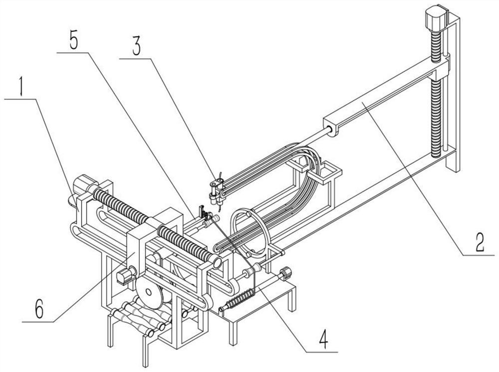
[0030] Such as Figure 1-8 As shown, a pipeline welding device includes a welding frame 1, a lifting mechanism 2, a welding mechanism 3, a winding mechanism 4, an adjusting mechanism 5, and a grinding mechanism 6. The lifting mechanism 2 is connected to the front side of the welding frame 1, and the welding mechanism 3 is connected to the rear side of the lifting mechanism 2, the winding mechanism 4 is connected to the middle part of the welding frame 1, the adjustment mechanism 5 is connected to the middle part of the welding frame 1, and the grinding mechanism 6 is connected to the rear side of the welding frame 1. The invention can weld the inner and outer pipe walls of the pipeline. For some large-scale pipelines, the inside cannot be manually entered, so that the lifting mechanism can be driven to drive the welding mechanism to weld the outside and inside of the pipeline, reducing manual operations to enter the inside of the pipeline for welding and can improve welding. T...

specific Embodiment approach 2

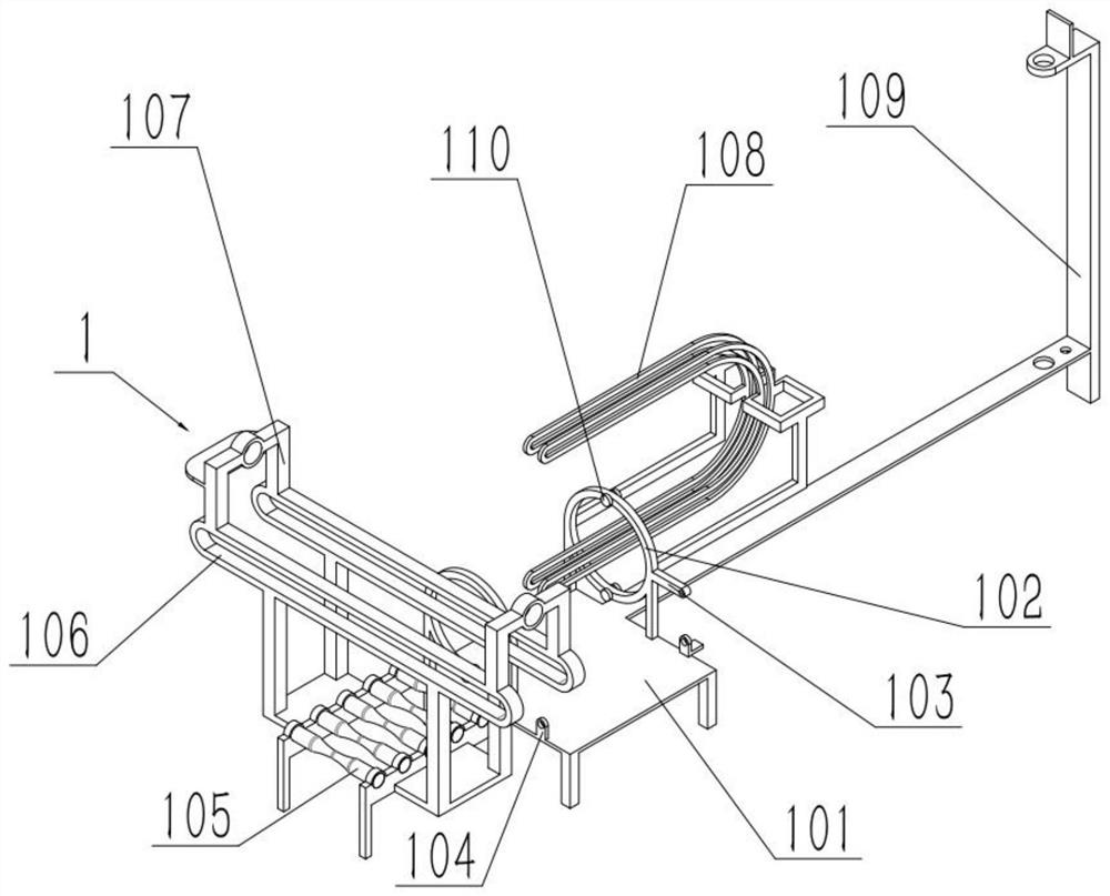
[0032] Such as Figure 1-8 As shown, a pipeline welding device, the welding frame 1 includes a main frame 101, a round frame 102, a round frame side frame 103, a side convex seat 104, a strip frame 106, a convex frame 107, an arc strip frame 108 and a front frame 109, a round frame 102 is respectively affixed to the front and rear sides of the middle part of the main frame 101, a round frame side frame 103 is fixed to the right end of each round frame 102, and a side protrusion is fixed to the front and rear ends of the right end of the middle part of the main frame 101. Seat 104, the front and rear ends of the main body frame 101 rear side upper end are fixedly connected with a strip frame 106 respectively, and two convex frames 107 are provided with, and the left and right ends of the two strip frames 106 upper ends are connected with the front and rear ends of the two convex frames 107 respectively. For fixed connection, the arc bar frame 108 is fixed on the round frame 102...

specific Embodiment approach 3

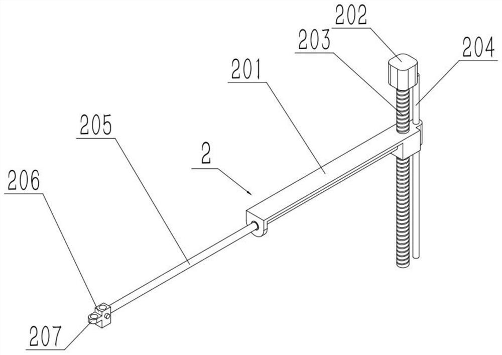
[0034] Such as Figure 1-8 As shown, a pipeline welding device, the lifting mechanism 2 includes a lifting seat 201, a motor I 202, a screw I 203, an electric push rod I 205, a welding handle frame 206 and a welding handle frame convex seat 207, the output shaft of the motor I 202 passes through the coupling The shaft device is fixedly connected to the lead screw I203, the front end of the lifting seat 201 is threadedly connected to the lead screw I203, the fixed end of the electric push rod I205 is fixed to the lifting seat 201, and the welding handle frame 206 is fixed to the movable part of the electric push rod I205. end, the welding handle frame protrusion 207 is set on the rear side of the welding handle frame 206, the lead screw I203 is rotatably connected to the front frame 109, the motor I202 is fixedly connected to the upper end of the front frame 109, and the welding handle frame 206 is slidably connected to the arc bar Box 108 on. When working, the driving motor I20...


PUM


Abstract

The invention relates to a welding device, in particular to a pipeline welding device. The pipeline welding device comprises a welding frame, a lifting mechanism, a welding mechanism, a winding mechanism, an adjusting mechanism and a grinding mechanism, wherein the lifting mechanism is connected to the front side of the welding frame, the welding mechanism is connected to the rear side of the lifting mechanism, the winding mechanism is connected to the middle of the welding frame, the adjusting mechanism is connected to the middle of the welding frame, and the grinding mechanism is connected to the rear side of the welding frame. According to the pipeline welding device, the inner and outer pipeline walls of pipelines can be welded, the lifting mechanism is driven to drive the welding mechanism to weld the exteriors and interiors of the pipelines aiming at the situation that workers cannot enter some large pipelines, manual operation entering the pipeline for welding is reduced, the welding safety can be improved, unknown dangers caused by the fact that the workers enter the pipeline are avoided, and the welding automation degree is improved.

Description

technical field [0001] The invention relates to a welding device, more specifically to a pipeline welding device. Background technique [0002] For example, Publication No. CN201922372119.2 Pipe Welding Device This utility model discloses a pipe welding device, which belongs to the field of welding technology. The pipeline welding device includes a welding trolley. The welding trolley includes a car body, a radio frequency reading module, a lifting mechanism and a welding mechanism. Magnetic rollers are rotatably installed on the bottom plate of the car body. The radio frequency reading module is arranged in the car body. The welding mechanism The lifting mechanism is installed on the side of the vehicle body, and the lifting mechanism is configured to drive the welding mechanism to move along the direction perpendicular to the bottom plate of the vehicle body; the pipeline welding device also includes a radio frequency tag module for setting on the pipeline to be welded. T...

Claims


Application Information

Patent Timeline
Patent Type & Authority Applications(China)
IPC IPC(8): B23K37/053B23K37/00B23K101/06
CPCB23K37/00B23K37/053B23K2101/06
Inventor 曹庆丰
Owner 曹庆丰
Why Eureka
Try Eureka