
Portable new energy automobile bumper device

A new energy vehicle, portable technology, applied in portable braking systems, vehicle parts, transportation and packaging, etc., can solve the problems of complex structure design, insufficient structural strength, inconvenient and stable clamping of the vehicle stop device, and avoid industrial accidents. , Enhanced security, convenient adjustment effect

Pending Publication Date: 2021-04-13
王正国
View PDF6 Cites 5 Cited by
  • Summary
  • Abstract
  • Description
  • Claims
  • Application Information

AI Technical Summary

Problems solved by technology

[0003] However, the structure design of the bumper device designed by the above-mentioned patent is complicated and unreasonable, and it is inconvenient to be firmly clamped on the outside of the wheel. The structural strength is insufficient and easy to deform, and it is inconvenient to provide sufficient forward resistance for the wheel. Therefore, we propose a portable new energy vehicle bumper. The device is used to solve the above problems

Method used


Image

  • Portable new energy automobile bumper device
  • Portable new energy automobile bumper device
  • Portable new energy automobile bumper device

Examples


Embodiment Construction

[0029] The following will clearly and completely describe the technical solutions in the embodiments of the present invention with reference to the accompanying drawings in the embodiments of the present invention. Obviously, the described embodiments are only some, not all, embodiments of the present invention.

[0030] In describing the present invention, it should be understood that the terms "upper", "lower", "front", "rear", "left", "right", "top", "bottom", "inner", " The orientation or positional relationship indicated by "outside", etc. is based on the orientation or positional relationship shown in the drawings, and is only for the convenience of describing the present invention and simplifying the description, rather than indicating or implying that the referred device or element must have a specific orientation, so as to Specific orientation configurations and operations, therefore, are not to be construed as limitations on the invention.

[0031] refer to Figure ...


PUM


Abstract

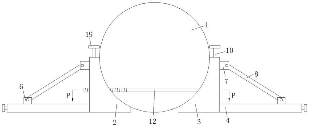
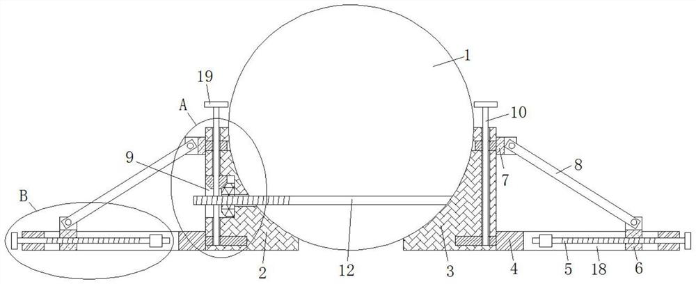
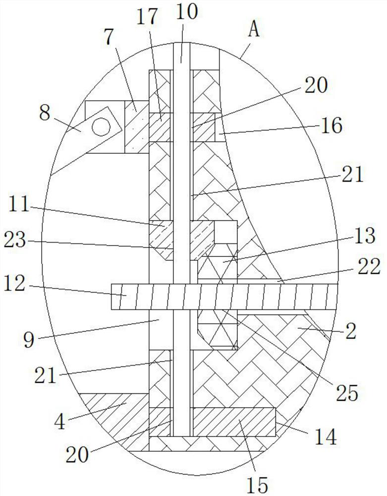
A portable new energy automobile bumper device is disclosed in the invention, and comprises a wheel, a front baffle and a rear baffle, the front baffle and the rear baffle are located on the two sides of the wheel correspondingly, bottom plates are detachably connected to the bottoms of the sides, away from each other, of the front baffle and the rear baffle correspondingly, rectangular holes are formed in the tops of the bottom plates, and horizontally-arranged first screws are rotatably connected into the rectangular holes; a sliding plate sleeves the outer side of the first screw in a threaded mode, rotating bases are detachably connected to the tops of the sides, away from each other, of the front baffle and the rear baffle, the rotating bases located on the same side of the wheels and the sliding plate are rotationally connected with the same traction rod, and first inserting grooves are formed in the bottoms of the sides, away from each other, of the front baffle and the rear baffle; and the sides, close to each other, of the two bottom plates are fixedly connected with one ends of first inserting rods. The device is reasonable in design, the distance between the front baffle and the rear baffle can be conveniently adjusted, the new energy automobile wheel can be stably clamped on the outer side of the wheel, advancing resistance of the new energy automobile wheel is effectively increased, industrial accidents caused by automobile self-starting are avoided, and the construction safety of workers is enhanced.

Description

technical field [0001] The invention relates to the technical field of new energy vehicle production, in particular to a portable new energy vehicle stop device. Background technique [0002] At present, with the continuous implementation of the national new energy policy and the continuous expansion of the scope of promotion, electric energy, as a new type of energy with special advantages such as no pollution, no noise, and no emissions, is more and more widely and expanded in domestic practical applications. Since the power source of the new energy vehicle is a motor, it can be started directly after connecting the battery, electric control, and motor terminals with a wiring harness without other external signal control. , The vehicle starts directly without any warning, which may cause unforeseen personal accidents and greater losses to the installers under the vehicle, the people working nearby and the surrounding items. After searching, the Chinese patent with the aut...

Claims


Application Information

Patent Timeline
Patent Type & Authority Applications(China)
IPC IPC(8): B60T3/00
CPCB60T3/00
Inventor 王正国
Owner 王正国
Learn More