Straight condensing unit with phase change energy storage

A pure condensing unit, phase change energy storage technology, applied in mechanical equipment, steam engine devices, engine components, etc., can solve problems such as high peak pressure

Pending Publication Date: 2021-04-13
润电能源科学技术有限公司
View PDF0 Cites 2 Cited by
  • Summary
  • Abstract
  • Description
  • Claims
  • Application Information

AI Technical Summary

Problems solved by technology

[0004] In view of this, the purpose of the present invention is to provide a pure condensing unit with phase change energy storage, which can effectively solve the problem of relatively large peak pressure

Method used


Image

  • Straight condensing unit with phase change energy storage
  • Straight condensing unit with phase change energy storage

Examples


Embodiment 1

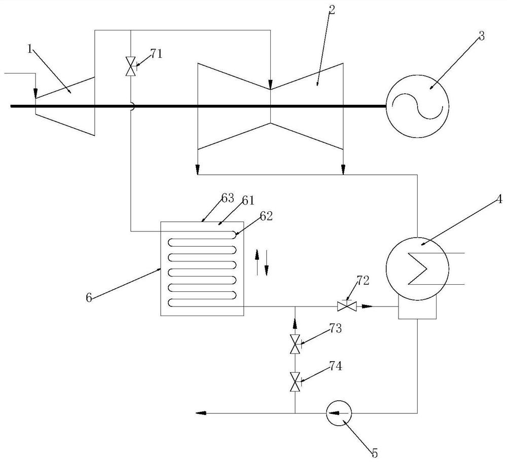
[0026] see figure 1 , figure 1 It is a schematic diagram of the piping structure of the pure condensing unit provided in Example 1 of the present invention.

[0027] In a specific embodiment, this embodiment provides a pure condensing unit with phase change energy storage, which may specifically be a deep peak regulation system of a pure condensing unit coupled with phase change energy storage, using coupled phase change energy storage The deep peak-shaving method of the pure condensing unit is used for peak-shaving work. Specifically, the pure condensing unit includes a steam turbine, a generator 3 , a condenser 4 , a phase change energy storage device 6 and a supply device 5 .

[0028] Among them, a rotary steam power device is installed inside the steam turbine. The high-temperature and high-pressure steam passes through the fixed nozzle to become an accelerated steam flow and is sprayed on the blades, so that the rotor equipped with blade rows rotates and at the same tim...

Embodiment 2

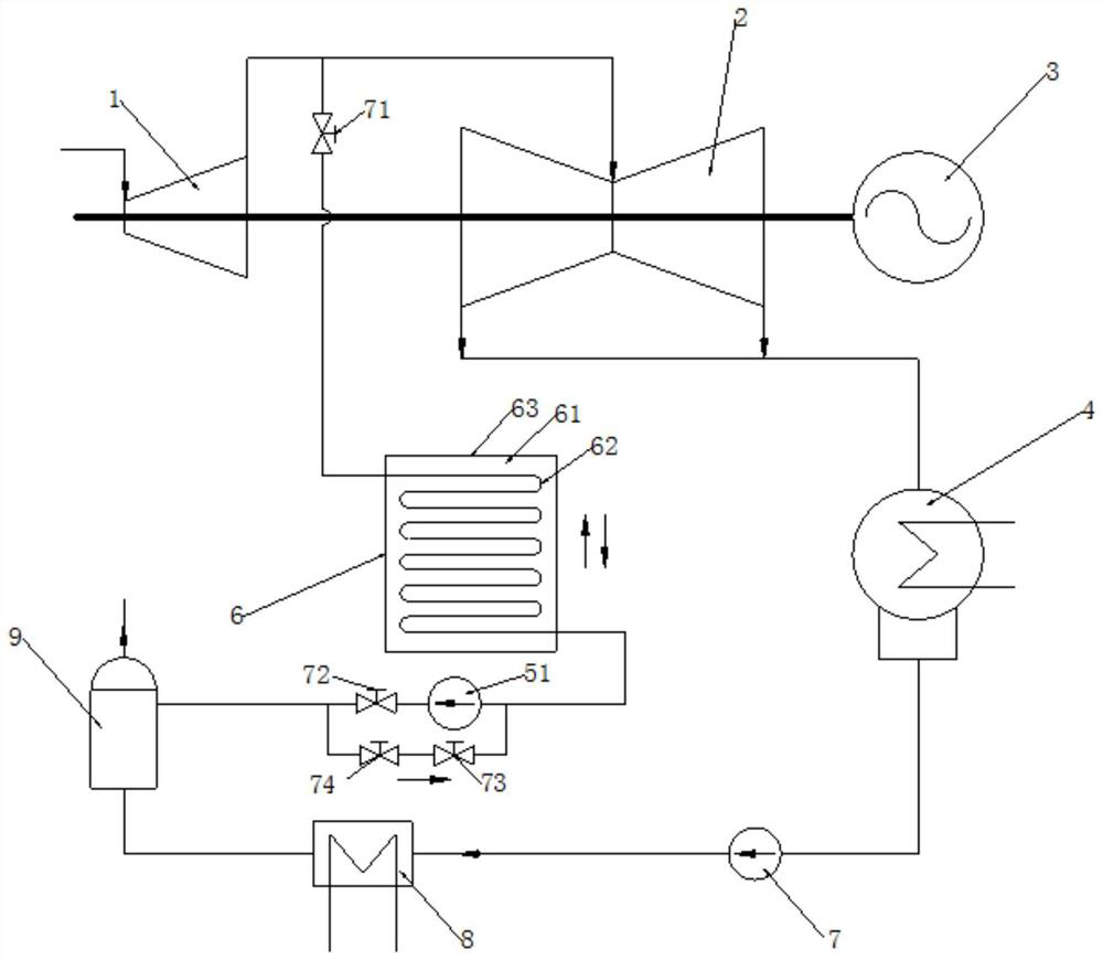
[0044] see figure 2 , figure 2 It is a schematic diagram of the piping structure of the pure condensing unit provided in Example 2 of the present invention.

[0045] Embodiment 2 is basically the same as the pure condensing unit in Embodiment 1. In this implementation, the connection mode of the high temperature port of the phase change energy storage device 6 and the internal structure of the phase change energy storage device 6 can refer to the above embodiment 1. How to supply liquid and how to discharge liquid to the low temperature port of the phase change energy storage device 6 in Embodiment 2 provides a new solution. Specifically, it is preferable that the supply device of the above-mentioned phase change energy storage device 6 is a deaerator 9, wherein the low temperature port communicates with the deaerator through an outflow channel and an inflow channel arranged in parallel with each other, so that the outflow channel can pass through, so that the low temperatu...


PUM


Abstract

The invention discloses a straight condensing unit with phase change energy storage. The straight condensing unit comprises a steam turbine, a generator in transmission connection with a rotating shaft of the steam turbine, a condenser communicating with a main outlet of the steam turbine and a phase change energy storage device capable of exchanging heat of internal flowing fluid and storing heat. A high-temperature port of the phase change energy storage device communicates with a steam inlet of a steam pressure cylinder of the steam turbine, a low-temperature port of the phase change energy storage device is connected with a supply device used for conveying fluid into the low-temperature port, and the low-temperature port is further connected with an energy storage and drainage switching valve. According to the straight condensing unit with the phase change energy storage, the phase change energy storage device can separate out a part of high-heat high-pressure fluid for heat storage in the valley period of a power grid, energy is released in the peak period of the power grid, and then the energy enters the steam turbine to convert heat energy into rotating mechanical energy to be output, so that correction and compensation are carried out on the peak-valley period of power utilization of the power grid, and the peak regulation pressure is reduced; and meanwhile, the energy utilization efficiency is improved.

Description

technical field [0001] The invention relates to the technical field of electric power equipment, and more specifically relates to a pure condensing unit with phase change energy storage. Background technique [0002] In recent years, with the rapid development of the economy, the installed capacity of the power grid has continued to expand, and the installed capacity of renewable energy such as wind energy and solar energy has grown rapidly. Due to the strong randomness and intermittency of renewable energy, the peak-to-valley difference of the power grid increases, and the peak-shaving pressure increases sharply, which seriously affects the safe and stable operation of the power grid. At present, the adjustment capacity of the power grid is difficult to adapt to the large-scale development and complete consumption of these renewable energy sources, resulting in serious abandonment of wind and light in some areas. Therefore, many areas urgently need to further tap the peak-...

Claims


Application Information

Patent Timeline
Patent Type & Authority Applications(China)
IPC IPC(8): F01D15/10F01D17/10F01K7/38F01K13/00F01K13/02F01K17/06F28D20/02
CPCF01D15/10F01D17/10F01K7/345F01K7/38F01K13/006F01K13/02F01K17/06F28D20/021Y02E60/14
Inventor 李源姜利辉毛睿任利明张小霓吴文龙
Owner 润电能源科学技术有限公司
Why Eureka
Try Eureka