A building automation temperature control device

A technology for building automation and temperature control equipment, applied in temperature control, non-electric variable control, control/regulation systems, etc., can solve problems such as ignition of flammable and explosive materials, fire, failure to cool down, etc., to reduce excessive friction or The effect of jamming, preventing potential safety hazards, and improving monitoring effects

Active Publication Date: 2022-04-15
一维(北京)工程技术有限责任公司
View PDF16 Cites 0 Cited by
  • Summary
  • Abstract
  • Description
  • Claims
  • Application Information

AI Technical Summary

Problems solved by technology

[0002] Fire is a phenomenon that people are often exposed to. Some are caused by improper human behavior, and some are caused by too dry weather, which causes the flammable and explosive materials in the building to catch fire, which leads to the fire. If it is not handled in time , the fire will spread slowly, and the prior art has the following defects: only when a fire breaks out in a building, the fire-fighting device can start to spray water to eliminate the fire, and when the building is irradiated by high-temperature sunlight, As a result, the building absorbs heat energy, causing the indoor temperature to rise sharply. If flammable and explosive materials are placed in the room, it will cause spontaneous combustion, resulting in unnecessary fires
[0004] However, the temperature sensor in the above technology can only measure the temperature of the wall at a single point. Due to the influence of light or other human factors, there are differences in the temperature of different areas on the wall at different positions. The thermostat cannot fully and effectively monitor the wall, and at the same time, when the local temperature of the wall is too high, it cannot be targeted to cool it down, thus affecting the use effect of the temperature control equipment

Method used


Image

  • A building automation temperature control device
  • A building automation temperature control device
  • A building automation temperature control device

Examples


Embodiment approach

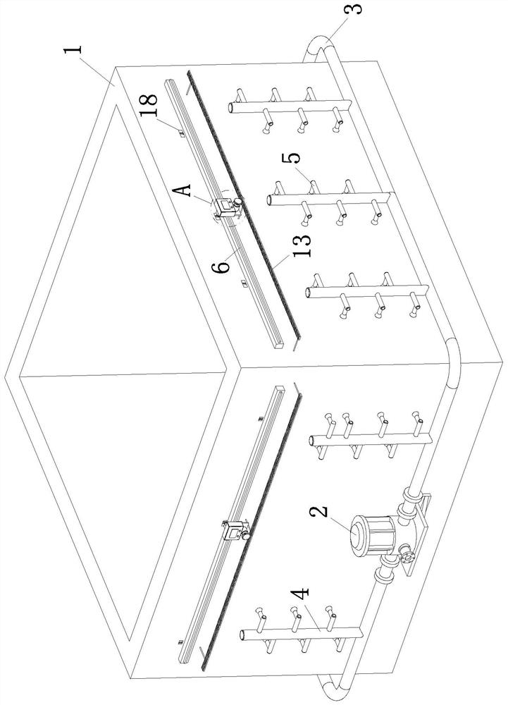
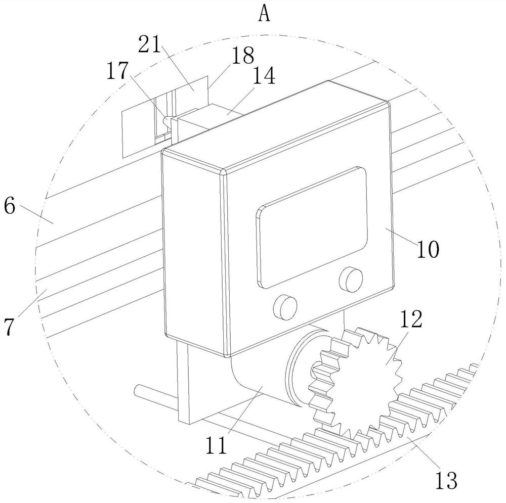
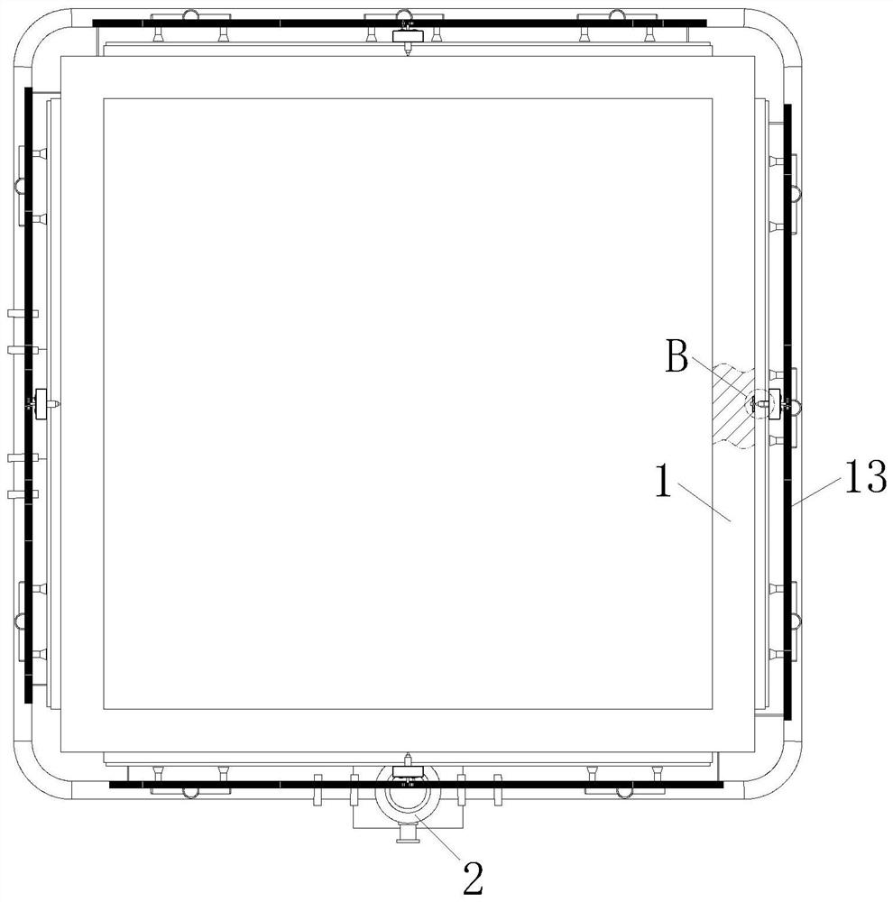
[0027] As an embodiment of the present invention, the wall 1 is opened at a position corresponding to the temperature temperature probe 17, and the support block 15 is made of a magnetic material, and the An electromagnet 19 is mounted inside the lumen 14; when operating, the temperature-sensing probe 17 is moved to the temperature-sensing slit 18, at this time, when the temperature warm probe 17 is moved to the temperature of the temperature, the temperature warm probe 17 is in the spring 16. The effect is inserted inside the temperature measurement tank 18 and detects the temperature inside the wall 1 to prevent the temperature of the temperature-temperature probe 17 from detecting the temperature of the outer temperature and interference when the surface detection temperature is detected. It is more accurate and valid when working, and when the temperature warm probe 17 needs to move to another temperature slide 18, the controller controls the electromagnet 19 to operate and at...


PUM


Abstract

The invention belongs to the technical field of temperature control equipment, in particular to a building automation temperature control equipment, including a wall and a water pump; the water pump is connected with a main water pipe and a water distribution pipe, and the water distribution pipes are respectively equipped with control valves, A slide rail is connected to the side wall of the wall, and a convex groove is opened inside the slide rail, and a slider is slidably connected to the inside of the convex groove, and a temperature sensor is connected to the outer end of the slider. A motor is installed at the bottom of the temperature sensor, a gear is connected to the end of the motor through a rotating shaft, a rack is connected to the side wall of the wall, and a sliding cavity is connected to the top of the temperature sensor, and the sliding cavity slides inside. Connected with a support block and a temperature-sensing probe; the present invention drives the temperature sensor to monitor the temperature of the wall in multiple directions through the set driving mechanism, preventing potential safety hazards caused by excessive local temperature of the wall, and at the same time achieving higher temperature The fixed-point cooling effect of the wall at the place greatly improves the monitoring effect of the temperature control equipment on the wall.

Description

Technical field [0001] The present invention belongs to the technical field of temperature control equipment, which is specifically a building automation temperature control equipment. Background technique [0002] The fire is a phenomenon that people often contact, and some are caused by improper behavior. Some are due to the weather is too dry, and the flammable and explosive of the building can cause the fire to initiate, if it is not treated in time The fire will slowly spread, the existing technology has the following defects: Only when the building is fire, the fire device can start the injection of the water source will be eliminated, and when the building is irradiated with high temperature in the sun, Increased building to absorb heat, which causes the indoor temperature to rise sharply. If the room is placed in the room, it will cause self-ignition, resulting in unnecessary fire. [0003] There have also been technical solutions for building automation temperature contr...

Claims


Application Information

Patent Timeline
Patent Type & Authority Patents(China)
IPC IPC(8): G05D23/20
CPCG05D23/20
Inventor 杜亚宁
Owner 一维(北京)工程技术有限责任公司
Why Eureka
Try Eureka