Microstrip fan-shaped array cascade decoupling circuit

A decoupling circuit and fan-shaped technology, applied in the direction of circuits, electrical components, waveguides, etc., can solve problems such as poor results

Active Publication Date: 2021-04-13
BEIJING UNIV OF TECH
View PDF8 Cites 0 Cited by
  • Summary
  • Abstract
  • Description
  • Claims
  • Application Information

AI Technical Summary

Problems solved by technology

The effective operating frequency of traditional lumped parameter decoupling components is generally up to several hundred megahertz. However, the operating frequency of the chips we use to design integrated circuits is often in GHz, so the traditional lumped component power supply decoupling is in this Bands don't work well

Method used


Image

  • Microstrip fan-shaped array cascade decoupling circuit
  • Microstrip fan-shaped array cascade decoupling circuit
  • Microstrip fan-shaped array cascade decoupling circuit

Examples


Embodiment Construction

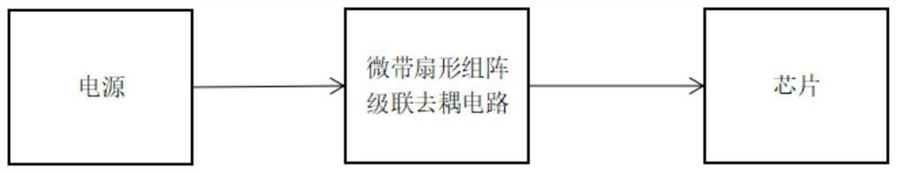
[0017] exist Figure 5 Among them, a microstrip fan array cascade decoupling circuit is composed of multiple sets of high-impedance microstrip lines and multiple sets of fan arrays, and a set of high-impedance microstrip lines and the fan array before the microstrip line constitute a first-level decoupling circuit. The unit has four levels of decoupling units in total, and the four levels of decoupling units are cascaded to form a microstrip sector array cascaded decoupling circuit. The dielectric material of the microstrip line of the microstrip fan array cascade decoupling circuit is FR4, the thickness of the dielectric material is 1mm, the dielectric constant is 4.4, the tangent loss value is 0.02, the material of the microstrip line is copper, and the thickness of copper is is 0.05mm, and the characteristic impedance of all high-impedance microstrip lines is 100 ohms.

[0018] In the specific examples above, such as Figure 5 As shown, the integrated circuit power port i...


PUM


Abstract

The invention discloses a microstrip fan-shaped array cascade decoupling circuit, which is composed of a plurality of groups of microstrip lines and fan-shaped lines and a dielectric substrate, wherein one group of high-resistance microstrip lines and one group of fan-shaped arrays form a primary decoupling unit, and the microstrip fan-shaped array cascade decoupling circuit is formed by cascading four stages of decoupling units. The microstrip fan-shaped array cascade decoupling circuit is used for decoupling an integrated circuit power supply, and can prevent a radio frequency alternating current signal from being coupled to other chips through the port of the power supply so as not to influence the operation of the whole circuit. The effective decoupling bandwidth of the microstrip fan-shaped array cascade decoupling circuit is 1-4 GHz, and the S21 between the power supply and the chip in the frequency band is less than -70 db, so that a radio frequency alternating current signal can be effectively prevented from being coupled to other chips through the power supply.

Description

technical field [0001] The invention relates to the field of power supply integrity design, in particular to a broadband microstrip sector array cascaded decoupling circuit. Background technique [0002] In modern communication systems, the transmitter and receiver are often powered by the same set of DC power supply. The problem brought about by this is that the high-power transmission signal may be coupled into the receiver through the DC power supply. Due to the excessive power of the transmission signal, the receiver is blocked, thus Loss of ability to receive small signals. As electronic devices operate at higher frequencies, the frequency of signals coupled into the power path also increases. The effective operating frequency of traditional lumped parameter decoupling components is generally up to several hundred megahertz. However, the operating frequency of the chips we use to design integrated circuits is often in GHz, so the traditional lumped component power supp...

Claims


Application Information

Patent Timeline
Patent Type & Authority Applications(China)
IPC IPC(8): H01P3/08
CPCH01P3/08
Inventor 赛景波吕明张繁军
Owner BEIJING UNIV OF TECH
Why Eureka
Try Eureka