Multiband antenna with cross-band scattering suppression function
A multi-band antenna and functional technology, which is applied to antennas, antenna coupling, and devices that enable antennas to work in different bands at the same time, can solve the problem of high-frequency sub-antenna radiation pattern distortion, deterioration of multi-band antenna performance, and adverse effects on user experience and other problems, to achieve the effect of suppressing scattering interference, good scattering suppression effect, and ensuring consistency
- Summary
- Abstract
- Description
- Claims
- Application Information
AI Technical Summary
Problems solved by technology
Method used
Image
Examples
Embodiment 1
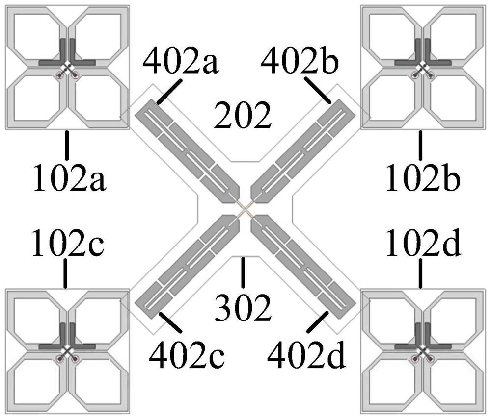
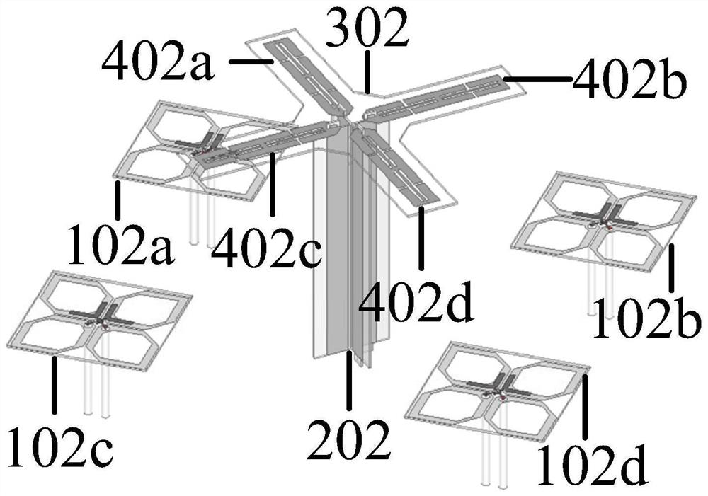
[0034] Such as figure 1 and figure 2 As shown, the multi-band antenna with cross-band scattering suppression function provided by this embodiment includes a low-frequency sub-antenna 202 and four high-frequency sub-antennas 102a-102d, and the low-frequency sub-antenna 202 is located at the four high-frequency sub-antennas 102a In the middle of -102d, the low-frequency sub-antenna 202 and the four high-frequency sub-antennas 102a-102d work in different frequency bands. 1690MHz to 2690MHz; the low-frequency sub-antenna 202 has four radiating arms 402a-402d, and the radiating arms 402a-402d are designed on the dielectric substrate 302, and the four radiating arms 402a-402d of the low-frequency sub-antenna 202 have the same physical structure. It is understood that the rotation of the radial arms 402a-402d in space does not affect their physical structural consistency. Such as image 3 As shown, the radiation arm 402a is divided into three arm sections 502a-502c, the arm secti...
Embodiment 2
[0038] Such as Figure 8As shown, the multi-band antenna with cross-band scattering suppression function provided by this embodiment includes a low-frequency sub-antenna 203 and four high-frequency sub-antennas 103a-103d, and the low-frequency sub-antenna 203 is located at the four high-frequency sub-antennas 103a In the middle of -103d, the low-frequency sub-antenna 203 and the four high-frequency sub-antennas 103a-103d work in different frequency bands, and the four radiation arms 403a-403d of the low-frequency sub-antenna 203 have the same physical structure. It should be understood that the radiation The rotation of the arms 403a-403d in space does not affect their physical conformity. Such as Figure 9 As shown, the radiation arm 403a is divided into three arm sections 503a-503c, the arm section 503a and the arm section 503b are electrically connected through the decoupling structure 603a, and the arm section 503b and the arm section 503c are electrically connected throu...
Embodiment 3
[0040] Such as Figure 11 As shown, the multi-band antenna with cross-band scattering suppression function provided by this embodiment includes a low-frequency sub-antenna 204 and four high-frequency sub-antennas 104a-104d, and the low-frequency sub-antenna 204 is located at the four high-frequency sub-antennas 104a In the middle of -104d, the low-frequency sub-antenna 204 and the four high-frequency sub-antennas 104a-104d work in different frequency bands, and the four radiation arms 404a-404d of the low-frequency sub-antenna 204 have the same physical structure. It should be understood that the rotation of the radiation arms 404a-404d in space does not affect the consistency of their physical structure. Such as Figure 12 As shown, the radiation arm 404a is divided into three arm sections 504a-504c, the arm section 504a is electrically connected to the arm section 504b through the decoupling structure 604a, and the arm section 504b and the arm section 504c are electrically ...
PUM
 Abstract
Description
Claims
Application Information
 - R&D
- Intellectual Property
- Life Sciences
- Materials
- Tech Scout
- Unparalleled Data Quality
- Higher Quality Content
- 60% Fewer Hallucinations
Browse by: Latest US Patents, China's latest patents, Technical Efficacy Thesaurus, Application Domain, Technology Topic, Popular Technical Reports.
© 2025 PatSnap. All rights reserved.Legal|Privacy policy|Modern Slavery Act Transparency Statement|Sitemap|About US| Contact US: help@patsnap.com


