Dual-polarized electromagnetic stealth antenna for pilot frequency decoupling

A dual-polarization, antenna technology, applied in the direction of antenna, antenna coupling, antenna components, etc., can solve the problems of cross-band scattering interference, deterioration of high-frequency sub-antenna performance radiation characteristics, deterioration of multi-band antenna performance, etc., to ensure consistency the effect of reducing scattering interference

Pending Publication Date: 2022-01-21
SOUTH CHINA UNIV OF TECH
View PDF6 Cites 0 Cited by
  • Summary
  • Abstract
  • Description
  • Claims
  • Application Information

AI Technical Summary

Problems solved by technology

Each sub-antenna of the multi-band antenna is designed in a limited space, resulting in strong cross-band scattering interference between the sub-antennas of different frequency bands, which will seriously deteriorate the performance of the multi-band antenna, thus bringing bad user experience influences
Since the low-frequency antenna has a larger physical size than the high-frequency antenna, when the high-frequency sub-antenna is working, the high-frequency scattering current is easily induced on the radiation arm of the low-frequency sub-antenna, which will cause the performance of the high-frequency sub-antenna (especially the radiation characteristics )deterioration

Method used


Image

  • Dual-polarized electromagnetic stealth antenna for pilot frequency decoupling
  • Dual-polarized electromagnetic stealth antenna for pilot frequency decoupling
  • Dual-polarized electromagnetic stealth antenna for pilot frequency decoupling

Examples


Embodiment 1

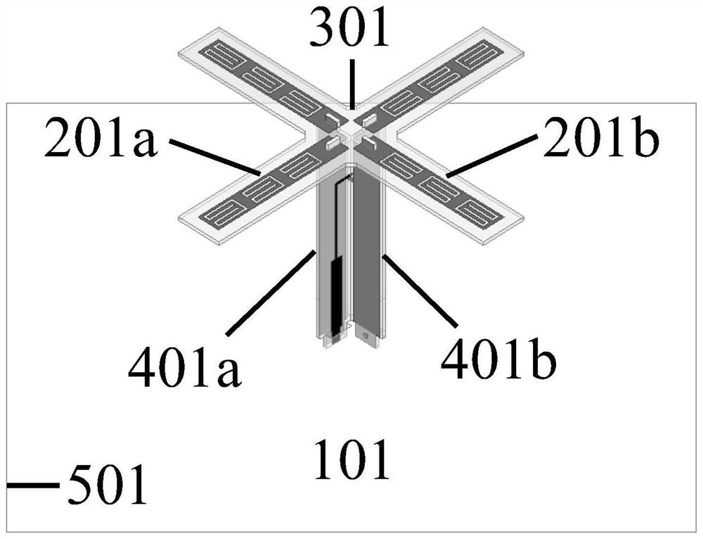
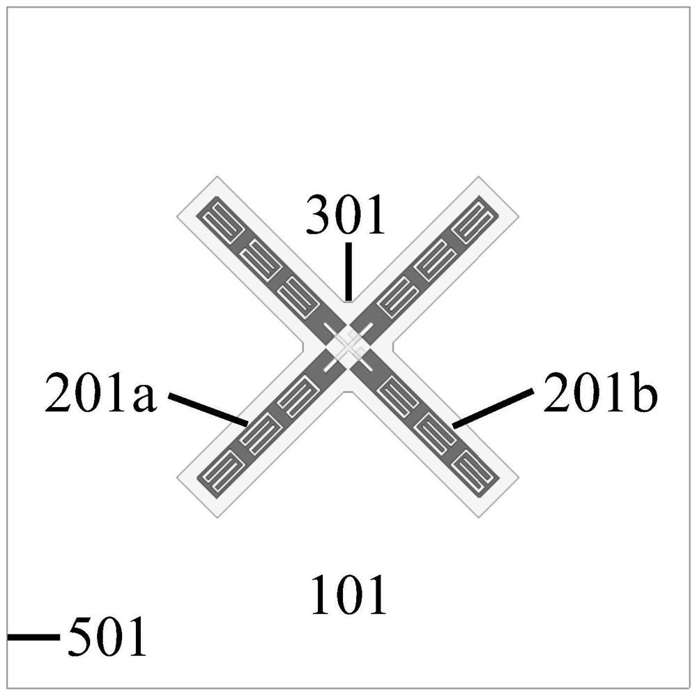
[0026] like figure 1 and figure 2 As shown, this embodiment provides a dual-polarized electromagnetic stealth antenna for inter-frequency decoupling ("electromagnetic stealth" means that the radar cross-section of the dual-polarized antenna in a specific frequency band is very small, so that The dual-polarized antenna is electromagnetically invisible to antennas operating in this specific frequency band), the antenna 101 includes two orthogonal radiating arms 201a, 201b, and the radiating arms 201a, 201b are designed on the dielectric substrate 301 Above, the dielectric substrate 301 is fixed on top of two orthogonal baluns 401a, 401b, the balun 401a is electrically connected to the radiating arm 201a, the balun 401b is electrically connected to the radiating arm 201b, and the two baluns 401a, 401b are vertically fixed on Metal launch plate 501.

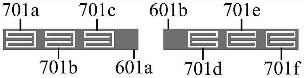
[0027] like image 3 As shown, it is a schematic structural diagram of the radiation arm 201a. The radiation arm 201b has the s...

Embodiment 2

[0031] like Figure 8 As shown, this embodiment provides a dual-polarized electromagnetic stealth antenna for inter-frequency decoupling. The antenna 102 includes two orthogonal radiating arms 202a, 202b, and the radiating arms 202a, 202b are designed on the dielectric substrate 302 Above, the dielectric substrate 302 is fixed on top of two orthogonal baluns 402a, 402b, the balun 402a is electrically connected to the radiating arm 202a, the balun 402b is electrically connected to the radiating arm 202b, and the two baluns 402a, 402b are vertically fixed on the metal on the launch board 502.

[0032] like Figure 9As shown, it is a schematic structural diagram of the radiation arm 202a. The radiation arm 202b has the same structure as the radiation arm 202a. The radiation arm 202a is divided into two arm segments 602a, 602b. The arm segment 602a is etched with opening resonant grooves 702a, 702b, the arm section 602b is etched with open resonant slots 702c and 702d, and the h...


PUM


Abstract

The invention discloses a dual-polarized electromagnetic stealth antenna for pilot frequency decoupling. The dual-polarized electromagnetic stealth antenna is used for suppressing cross frequency band scattering interference among multiband antennas. The antenna is mainly characterized in that opening resonance grooves (the number of the opening resonance grooves is enough to enable the opening resonance grooves to be distributed on the whole radiation arms) are etched on a pair of radiation arms which are crossed together, the action frequency band of the antenna is determined through the opening resonance grooves, and in the action frequency band, scattering currents on the radiation arms can be counteracted in the reverse direction near the opening resonance grooves, and the radar cross section of the antenna is close to zero so that scattering interference generated on the antenna working in the acting frequency band is inhibited, the electromagnetic stealth effect is further achieved, and finally, the antenna working in the specific frequency band obtains a stable radiation pattern.

Description

technical field [0001] The invention relates to the technical field of wireless communication, in particular to a dual-polarized electromagnetic stealth antenna for different-frequency decoupling. Background technique [0002] In recent years, the fifth generation (5G) communication technology has developed rapidly, and 2G / 3G / 4G networks are unlikely to exit in a short time, so 5G networks will provide services together with existing 2G / 3G / 4G networks. Due to the high operating frequency of 5G antennas, more 5G base stations need to be built to achieve signal coverage, which will exacerbate the current shortage of base station site resources and lead to an increase in the cost of 5G network construction. [0003] It is well known in the industry that multi-band antennas (here, especially multi-frequency common-aperture antennas) can effectively improve the space utilization of the antenna system and reduce the site rental cost of antenna equipment while providing more divers...

Claims


Application Information

Patent Timeline
IPC IPC(8): H01Q1/38H01Q1/52H01Q1/50H01Q19/10
CPCH01Q1/38H01Q1/52H01Q1/521H01Q1/50H01Q19/104
Inventor 褚庆昕常玉林蒋进
Owner SOUTH CHINA UNIV OF TECH
Why Eureka
Try Eureka