PDC drill bit matching tool
A drill bit and tool technology, which is applied in the field of PDC drill bit supporting tools, can solve the problems of debris clogging with mud balls, dense nozzles, and the use of slender tools, etc., achieving remarkable results and excellent operability.
- Summary
- Abstract
- Description
- Claims
- Application Information
AI Technical Summary
Problems solved by technology
Method used
Image
Examples
Embodiment 1
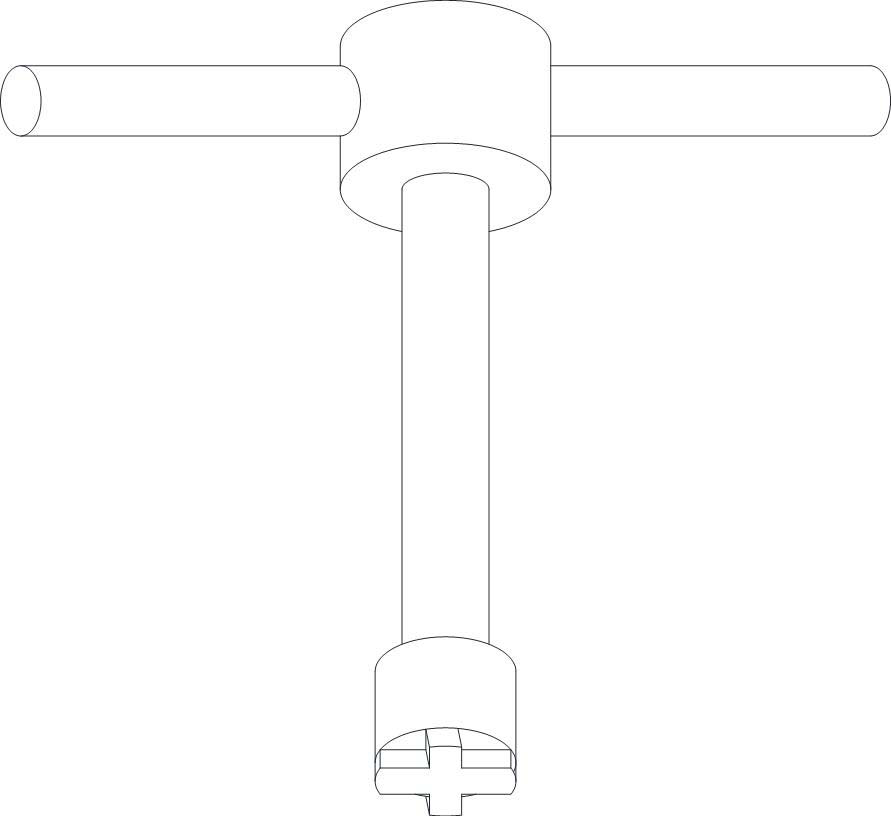
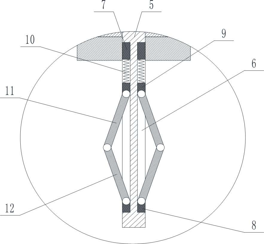
[0039] Such as Figure 2-Figure 4 A PDC drill supporting tool shown includes a connecting column 1, and the two ends of the connecting column 1 are respectively fixedly connected to the nozzle connector 2 and the end 3, and the bottom of the nozzle connector 2 is provided with a hole that matches the water hole of the drill bit. The cross protrusion 4 also includes a through hole, an inner column 5 inserted in the through hole, and the through hole runs through the terminal 3, the connecting column 1, the nozzle connection head 2, and the cross protrusion 4 in sequence, and the inner column 5 and the The through holes are screwed together; the outer wall of the inner column 5 close to the direction where the cross protrusion 4 is located has several annular uniform grooves 6, the axes of the grooves 6 are parallel to the axis of the inner column 5, and the grooves 6 The first positioning block 7 and the second positioning block 8 are respectively fixed at the upper and lower e...
Embodiment 2
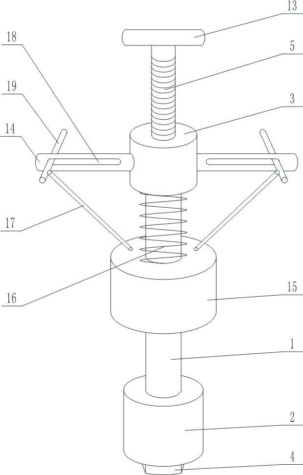
[0044] A PDC drill supporting tool, on the basis of Embodiment 1, the inner column 5 includes a screw section and a polished section distributed up and down, the screw section and the end 3 are threaded, and the groove 6 is arranged on the On the polished rod section. The top of the inner column 5 is fixed with a connection knob 13 .
[0045] Preferably, the length of the screw section can be set according to the stroke end point of the inner column moving up and down, so as to limit the movement range of the inner column.
Embodiment 3
[0047] A kind of PDC drill supporting tool, on the basis of any one of the above-mentioned embodiments, such as Figure 5 and Figure 6 As shown, it also includes a force application rod 14 passing through the terminal 3 , the force application rod 14 is fixedly connected with the terminal 3 , and the through hole passes through the force application rod 14 . It also includes a heavy hammer 15 movably sleeved outside the connecting column 1, the heavy hammer 15 is located between the nozzle connection head 2 and the end 3; when the heavy hammer 15 goes down to the low position of the stroke, it is connected with the nozzle Head 2 contacts. A second compression spring 16 is connected between the weight member 15 and the end 3 , and the second compression spring 16 is used to push the weight member 15 to move toward the nozzle connecting head 2 . It also includes a lifting mechanism for lifting the heavy hammer 15 , and the lifting mechanism moves the heavy hammer 15 to the di...
PUM
 Abstract
Description
Claims
Application Information
 - R&D
- Intellectual Property
- Life Sciences
- Materials
- Tech Scout
- Unparalleled Data Quality
- Higher Quality Content
- 60% Fewer Hallucinations
Browse by: Latest US Patents, China's latest patents, Technical Efficacy Thesaurus, Application Domain, Technology Topic, Popular Technical Reports.
© 2025 PatSnap. All rights reserved.Legal|Privacy policy|Modern Slavery Act Transparency Statement|Sitemap|About US| Contact US: help@patsnap.com


