
Method for manufacturing tire mold

A manufacturing method and mold technology, which are applied in the field of tire mold manufacturing, can solve the problems of reduced manufacturing efficiency of tire molds, deviation of slit exhaust port width, deviation of pattern of mold pieces, etc., so as to achieve the effect of improving manufacturing efficiency.

Active Publication Date: 2021-04-16
BRIDGESTONE CORP
View PDF5 Cites 0 Cited by
  • Summary
  • Abstract
  • Description
  • Claims
  • Application Information

AI Technical Summary

Problems solved by technology

In such tires, there is also a possibility that pattern shifts are likely to occur at the opposite parts of the mold sheet, resulting in deviations in the width of the slit vents
Therefore, the labor and time required to form the mold sheet increase, and the manufacturing efficiency of the tire mold also decreases.

Method used


Image

  • Method for manufacturing tire mold
  • Method for manufacturing tire mold
  • Method for manufacturing tire mold

Examples


no. 1 Embodiment approach

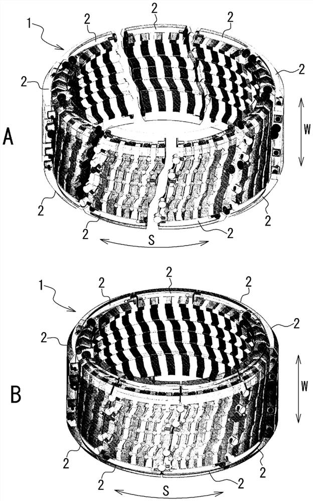
[0040] figure 1 It is a perspective view showing the tire mold 1 of the first embodiment, showing the structure of the tire mold 1 seen through. in addition, figure 1 A shows the tire mold 1 in an open state, figure 1 B shows the tire mold 1 in a closed state.

[0041] As shown in the figure, the tire mold 1 is an annular outer mold for molding the outer surface of a tire, and is provided in a tire molding device (tire vulcanizing device). The tire mold 1 surrounds an annular tire and molds the outer peripheral portion including the tread portion of the tire. Regarding the direction of the tire mold 1 , the width direction of the tire mold 1 (mold width direction W) coincides with the tire width direction, and the circumferential direction of the tire mold 1 (mold circumferential direction S) coincides with the tire circumferential direction. In addition, the radial direction of the tire mold 1 (mold radial direction) coincides with the tire radial direction.

[0042] ...

no. 2 Embodiment approach

[0074] Next, a method for manufacturing the tire mold 1 according to the second embodiment will be described. Regarding the manufacturing method of the tire mold 1 of the second embodiment, the description of the same items as those of the manufacturing method of the tire mold 1 of the first embodiment will be omitted. In addition, regarding the configuration of the second embodiment, the same names as those of the configuration of the first embodiment are used for configurations corresponding to the configuration of the first embodiment.

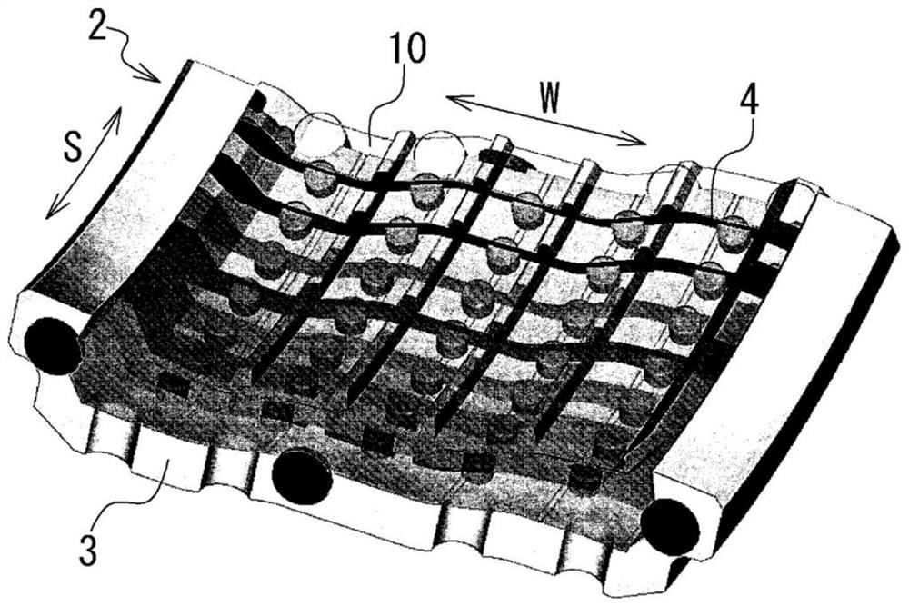
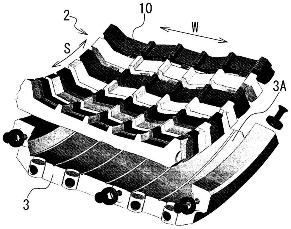
[0075] Figure 14 It is a perspective view showing the mold half 2 of the second embodiment, showing the structure of the mold half 2 through the mold half 2 . Figure 15 It is a disassembled perspective view showing the mold half 2 of the second embodiment. Figure 16 It is a perspective view showing the mold sheet 10 of the second embodiment, and shows a part of the mold sheets 10 among the plurality of mold sheets 10 provided in the mo...


PUM


Abstract

The purpose of the present invention is to easily form a plurality of mold pieces forming a slit vent and to improve the manufacturing efficiency of a tire mold. The mold pieces mold a tire by means of molding parts thereof in a state in which a slit vent is formed between mutual slit forming parts. The plurality of mold pieces are formed of a mold material (30). On a back surface part (31) side of the mold material (30), a plurality of dividing grooves (33) wider than the slit vent are formed along dividing positions of the plurality of mold pieces. The mold material (30) is cut by laser at the bottoms of the plurality of dividing grooves (33) to divide the plurality of mold pieces, and a slit forming part is formed on the molding part side of the plurality of mold pieces.

Description

technical field [0001] The present invention relates to a method of manufacturing a tire mold having a plurality of mold pieces. Background technique [0002] In a tire mold having a plurality of mold pieces, the plurality of mold pieces are combined into a ring shape, and a tire is molded by using the plurality of mold pieces. The tire is vulcanized while being pressed against a plurality of mold sheets. At this time, air may be enclosed between the tire and the mold sheet. In particular, in the case of a mold sheet for molding the tread portion of a tire, a closed space is formed between the mold sheet and the tire due to the protrusions of the mold sheet corresponding to the grooves of the tire, so air is easily trapped. . [0003] In order to prevent air from being trapped, the tire mold usually has an air discharge portion (exhaust portion), and the air is discharged from the air discharge portion. However, when the air discharge portion is a vent hole, rubber enter...

Claims


Application Information

Patent Timeline
Patent Type & Authority Applications(China)
IPC IPC(8): B29C33/02B29C33/10B29C33/38B29C35/02B29K21/00
CPCB29C33/02B29C33/10B29C35/02B29C33/38
Inventor 石原泰之
Owner BRIDGESTONE CORP
Learn More