An infrared differential pressure puffing drying equipment and process for fruits and vegetables
A puffing drying, infrared technology, applied in application, food science, food forming, etc., can solve the problems of high volume demand and large space occupation of vacuum tanks, and achieve cost-effective control, simple installation, and uniform radiation intensity. Effect
- Summary
- Abstract
- Description
- Claims
- Application Information
AI Technical Summary
Problems solved by technology
Method used
Image
Examples
Embodiment 1
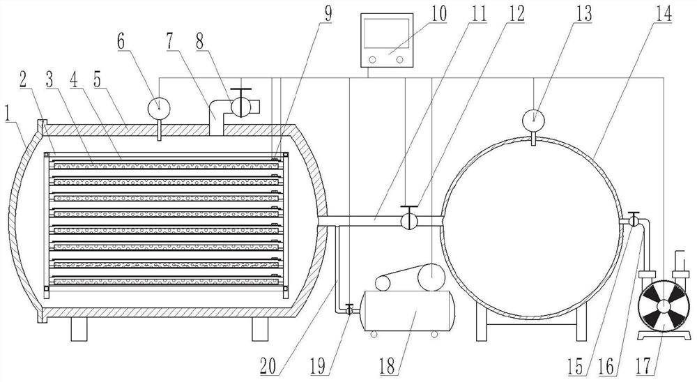
[0051] In a typical embodiment of the present invention, refer to figure 1 As shown, a fruit and vegetable infrared differential pressure puffing drying equipment includes an expansion tank, and several layers of material racks are arranged in the expansion tank, and the material racks are used to support the material tray, and the expansion tank is provided with a first pressure sensor; The heating element above each tray, the heating element is equipped with a temperature sensor; the pressurization component, the pressurization component is connected with the expansion tank through the pipeline; the pressure relief component, the pressure relief component is connected with the expansion tank; the pressure reduction component, the pressure reduction component is connected with the The expansion tank is connected, and the depressurization component is provided with the second pressure sensor; the central controller is independent of the first pressure sensor, the second pressur...
Embodiment 2
[0067] This example introduces an infrared pressure difference puffing drying method for fruits and vegetables, using the infrared pressure difference puffing and drying equipment for fruits and vegetables described in Example 1.
[0068] like figure 2 The shown fruit and vegetable infrared differential pressure puffing drying method is realized through the following steps:
[0069] Step ①, spread the pretreated and pre-dried fruit and vegetable raw materials on the material tray 3, and place them in the material rack 2 in the puffing chamber 5, close the door 1; turn on the power, start the central controller 10, set the first The first target pressure, the second target pressure, the target puffing temperature, the target drying temperature, and the target stagnation time, the central controller 10 controls the infrared radiation plate 4, the air compressor 18, and the vacuum pump 17 to start, and the second valve 15 is opened at the same time, and the drying enters the inc...
Embodiment 3
[0079] The difference between this embodiment and embodiment one is:
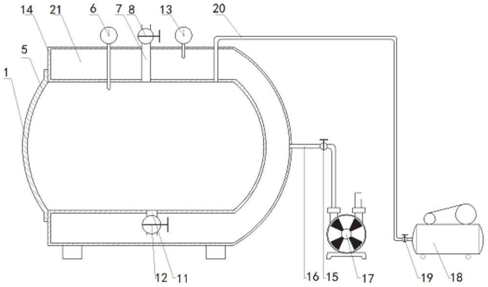
[0080] In order to reduce the footprint of the vacuum tank, the vacuum tank can be placed outside the expansion tank, refer to image 3 As shown, the vacuum tank surrounds the expansion tank except for the part outside the door, and a vacuum chamber 21 is formed between the vacuum tank and the expansion tank, and the main structure of the vacuum tank and the expansion tank is an integral structural part, so that the thermal insulation effect of the expansion tank is good. In addition to the setting of the pressure relief component and the pressure reduction component, a vacuum chamber is installed outside the expansion tank, which can further effectively solve the problems that the overall equipment occupies a large area and the thermal insulation effect of the expansion chamber is poor.
PUM
 Abstract
Description
Claims
Application Information
 - R&D
- Intellectual Property
- Life Sciences
- Materials
- Tech Scout
- Unparalleled Data Quality
- Higher Quality Content
- 60% Fewer Hallucinations
Browse by: Latest US Patents, China's latest patents, Technical Efficacy Thesaurus, Application Domain, Technology Topic, Popular Technical Reports.
© 2025 PatSnap. All rights reserved.Legal|Privacy policy|Modern Slavery Act Transparency Statement|Sitemap|About US| Contact US: help@patsnap.com


