Wearable equipment for rapidly measuring psychological pressure
A psychological pressure and rapid measurement technology, applied in psychological devices, measuring pulse rate/heart rate, etc., can solve problems affecting test results and wearing comfort, and achieve the effect of easy wearing, easy disassembly and installation, and convenient replacement
- Summary
- Abstract
- Description
- Claims
- Application Information
AI Technical Summary
Problems solved by technology
Method used
Image

Examples
Embodiment 1
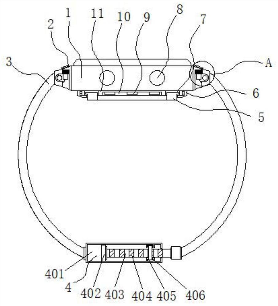
[0027] Example 1: See Figure 1-4 , a wearable device for quickly measuring psychological stress, comprising a dial 1, a detachment structure 2 is provided on both sides of the dial 1, a watch strap 3 is provided on one side of the detachment structure 2, and a connecting structure 4 is provided at the bottom of the watch strap 3 , the bottom end of the dial 1 is provided with a heart rate and pulse sensor 9, two sets of adjustment buttons 8 are movably connected to the two ends of the dial 1, and the bottom end of the dial 1 is provided with a sweat-absorbing mechanism;
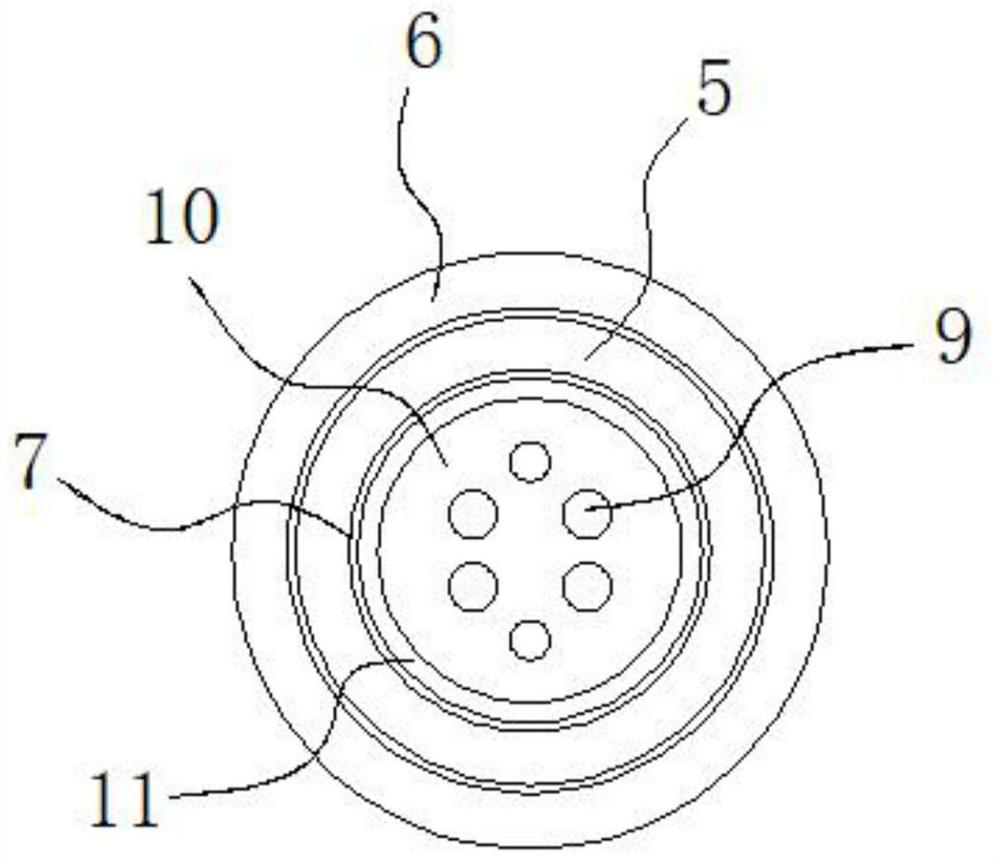
[0028] see Figure 1-4 , a wearable device for quickly measuring psychological stress also includes a sweat-absorbing mechanism, the sweat-absorbing mechanism includes a chassis 11, the bottom of the chassis 11 is inlaid with a bottom groove 10, the bottom groove 10 is fixedly connected with the heart rate and pulse sensor 9, and the bottom of the chassis 11 Inlaid with a groove 7, the inside of the groove ...
Embodiment 2
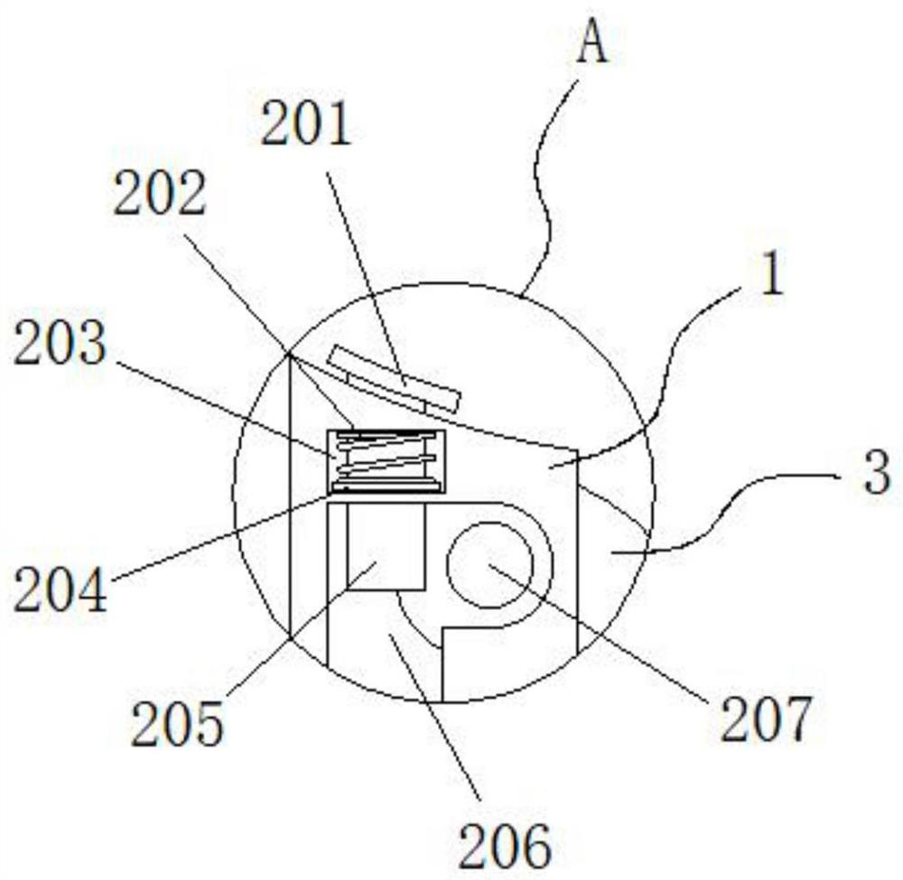
[0031] Embodiment 2: The disassembly structure 2 is composed of a pull plate 201, a first spring 202, a cavity 203, a mounting plate 204, a telescopic rod 205, a placement groove 206 and an installation shaft 207. The placement groove 206 is embedded on both sides of the bottom end of the dial 1, The mounting shaft 207 is fixedly connected to the top inside of the strap 3, the placement groove 206 is flexibly connected to the mounting shaft 207, the cavity 203 is arranged on both sides of the dial 1, and the inside of the cavity 203 is provided with a mounting plate 204, and the mounting plate 204 The interior is fixedly connected with a telescopic rod 205, the telescopic rod 205 is movably connected with the installation shaft 207, the top of the mounting plate 204 is fixedly connected with a first spring 202, the first spring 202 is fixedly connected with the cavity 203, and the telescopic rod 205 runs through the cavity 203. A pull plate 201 is fixedly connected to the top a...
Embodiment 3
[0034] Embodiment 3: The connection structure 4 is composed of a slot 401, a limiting plate 402, an insert 403, a card slot 404, a card plate 405, a chute 406, a fixed plate 407, a second spring 408, a pull rod 409 and a movable slot 410, The slot 401 is fixedly connected to the bottom end of one side of the strap 3, and the insertion strip 403 is fixedly connected to the bottom end of the other side of the strap 3. The insertion strip 403 runs through one side of the slot 401 and extends to the inside of the slot 401. One side of the insertion strip 403 is fixedly connected to the limiting plate 402, and one end of the insertion strip 403 is inlaid with multiple groups of card slots 404 at equal intervals, and a group of chute 406 is fixedly connected to the same side of the two ends of the slot 401, and the inside of the chute 406 A card board 405 is movably connected, and the card board 405 is movably connected with the card slot 404. One side of one end of the slot 401 is f...
PUM
 Abstract
Description
Claims
Application Information
 - Generate Ideas
- Intellectual Property
- Life Sciences
- Materials
- Tech Scout
- Unparalleled Data Quality
- Higher Quality Content
- 60% Fewer Hallucinations
Browse by: Latest US Patents, China's latest patents, Technical Efficacy Thesaurus, Application Domain, Technology Topic, Popular Technical Reports.
© 2025 PatSnap. All rights reserved.Legal|Privacy policy|Modern Slavery Act Transparency Statement|Sitemap|About US| Contact US: help@patsnap.com