
Electrical equipment drainage system and electrical equipment using same

A technology for electrical equipment and drainage system, which is applied in the direction of electrical equipment structural parts, electrical components, electric vehicle charging technology, etc. Increase the capacity and ensure the effect of normal operation

Pending Publication Date: 2021-04-20
TIANJIN PINGGAO INTELLIGENT ELECTRIC +2
View PDF6 Cites 0 Cited by
  • Summary
  • Abstract
  • Description
  • Claims
  • Application Information

AI Technical Summary

Problems solved by technology

[0005] The purpose of the present invention is to provide a drainage system for electrical equipment to solve the problem that the existing technology cannot meet the protection level requirements, and the cabinet door is directly drained, which causes the cabinet door to be dirty or even rusty, and at the same time, due to the limited volume of the water receiving tank. The problem of untimely drainage in case of sudden heavy rain; the purpose of the present invention is to provide an electrical device to solve the problem that the existing technology cannot meet the protection level requirements, and the cabinet door is directly drained, causing the cabinet door to be dirty or even rusted , At the same time, due to the limited volume of the water tank, the drainage is not timely in case of sudden heavy rain

Method used


Image

  • Electrical equipment drainage system and electrical equipment using same
  • Electrical equipment drainage system and electrical equipment using same
  • Electrical equipment drainage system and electrical equipment using same

Examples


Embodiment Construction

[0057] In order to make the object, technical solution and advantages of the present invention clearer, the present invention will be further described in detail below in conjunction with the accompanying drawings and embodiments. It should be understood that the specific embodiments described here are only used to explain the present invention, and are not intended to limit the present invention, that is, the described embodiments are only some of the embodiments of the present invention, but not all of the embodiments. The components of the embodiments of the invention generally described and illustrated in the figures herein may be arranged and designed in a variety of different configurations.

[0058] Accordingly, the following detailed description of the embodiments of the invention provided in the accompanying drawings is not intended to limit the scope of the claimed invention, but merely represents selected embodiments of the invention. Based on the embodiments of the...


PUM


Abstract

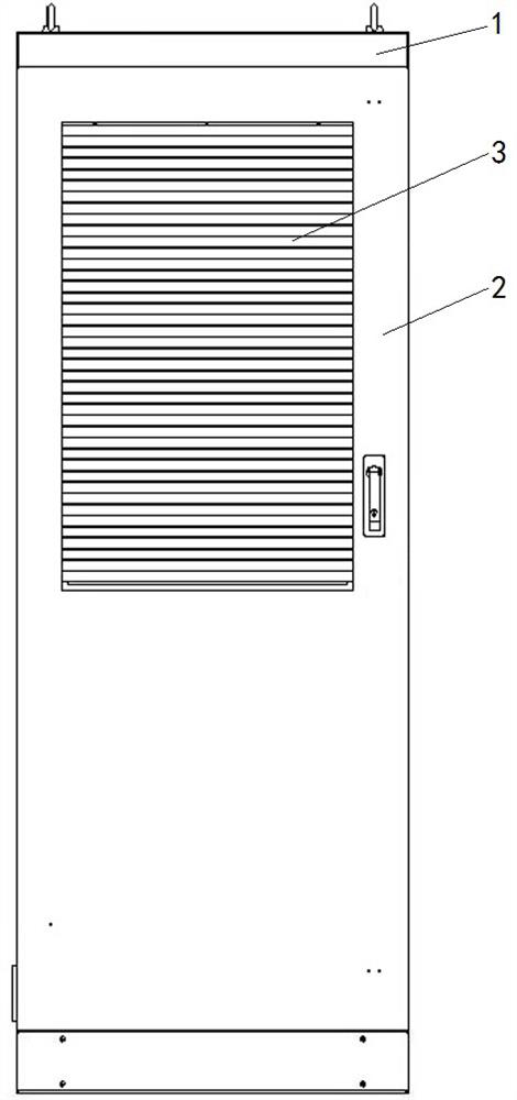
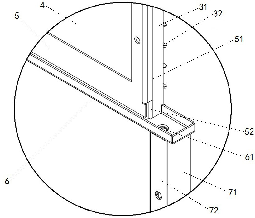
The invention provides an electrical equipment drainage system and electrical equipment using the same. The electrical equipment drainage system comprises a shutter structure, ventilation cotton arranged on the rear side of the shutter structure, a pressing plate arranged on the rear side of the ventilation cotton, a water receiving tank arranged below the ventilation cotton, and a drainage pipe; the bottom of the water receiving tank is provided with a water outlet for discharging water in the water receiving tank to the outside of the electrical equipment; and the drainage pipe is provided with a first end communicating with the drainage port and a second end extending out of the electrical equipment, dustproof cotton is arranged in the second end, a bottom cover is further installed, the dustproof cotton is located on the inner side of the bottom cover, and screen holes allowing water to flow out are formed in the bottom cover. According to the invention, water in the water receiving tank is discharged to the outside of the electrical equipment through the drain pipe, so that the cabinet door is prevented from being dirty or rusted due to direct drainage from the cabinet door; the drainage pipe increases the water containing capacity, and the situation that suddenly increased water cannot be drained in time and flows into equipment is avoided; and the dustproof cotton can prevent external dust from entering the equipment, thereby ensuring that the electrical equipment meets the protection grade requirement.

Description

technical field [0001] The invention relates to the technical field of electrical equipment manufacturing, in particular to an electrical equipment drainage system and electrical equipment using the drainage system. Background technique [0002] The charging facility is a charging system that ensures the safe, reliable, and economical supply of electric energy for electric vehicles and the grid, and an outdoor electrical device that uses the charging device as a carrier to realize the interaction between electric vehicles and the grid. The protection level (IP54, IP55) of the shell in the charging equipment and the heat dissipation of the equipment form two contradictory and opposite technical difficulties. Under the premise that the equipment reaches the protection level, the internal heat dissipation of the equipment becomes a technology for the safe and stable operation of the charging equipment problem. [0003] The Chinese utility model patent with the authorized notif...

Claims


Application Information

Patent Timeline
IPC IPC(8): B60L53/31H05K7/00
CPCY02T10/70Y02T10/7072Y02T90/12Y02T90/16
Inventor 王爽吴登丰宇庭王茜丛艳伟汪宁张罗锐张敬涛桑永建薛莲
Owner TIANJIN PINGGAO INTELLIGENT ELECTRIC
Features
  • Generate Ideas
  • Intellectual Property
  • Life Sciences
  • Materials
  • Tech Scout
  • Unparalleled Data Quality
  • Higher Quality Content
  • 60% Fewer Hallucinations
Learn More