Brake control method, device and system

A braking control and braking force technology, applied in braking safety systems, braking transmissions, brakes, etc., can solve problems such as affecting vehicle driving safety, braking distance and braking response time, etc.

Active Publication Date: 2021-04-20
精诚工科汽车系统有限公司
View PDF7 Cites 3 Cited by
  • Summary
  • Abstract
  • Description
  • Claims
  • Application Information

AI Technical Summary

Problems solved by technology

[0006] In view of this, the present invention aims to propose a braking control method, device and system to solve the problem of the braking distance and the braking distance easily caused by the existence of the decoupling gap when the executive mechanism of the existing decoupling electronic brake booster fails. The brake response time is long, which affects the driving safety of the vehicle

Method used


Image

  • Brake control method, device and system
  • Brake control method, device and system
  • Brake control method, device and system

Examples


Embodiment Construction

[0060] Embodiments of the present application will be described in more detail below with reference to the accompanying drawings. Although the embodiments of the present application are shown in the drawings, it should be understood that the present application can be embodied in various forms and should not be limited by the embodiments set forth herein. Rather, these embodiments are provided so that this application can be understood more thoroughly, and will fully convey the scope of this application to those skilled in the art.

[0061] It should be noted that, in the case of no conflict, the embodiments of the present invention and the features in the embodiments can be combined with each other.

[0062] The present invention will be described in detail below with reference to the accompanying drawings and examples.

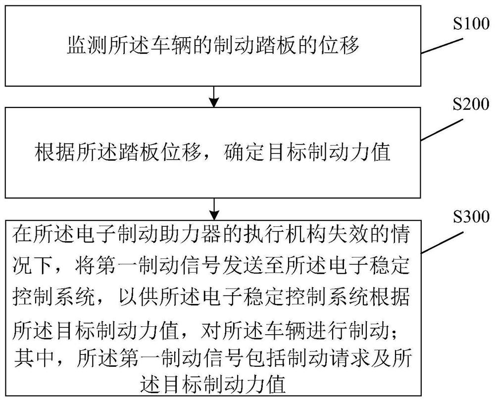
[0063] see figure 2 , which shows a schematic flow chart of a brake control method provided by an embodiment of the present invention. The brake control ...


PUM


Abstract

The invention provides a brake control method, device and system, the method is applied to a decoupling type electronic brake booster of a vehicle, the vehicle further comprises an electronic stability control system, and the method comprises the steps of monitoring the displacement of a brake pedal of the vehicle; determining a target braking force value according to the displacement; under the condition that it is determined that an executing mechanism of the electronic brake booster fails, sending a first brake signal is sent to the electronic stability control system, so that the electronic stability control system responds to a brake request and brakes the vehicle according to the target brake force value, wherein the first braking signal comprises the braking request and the target braking force value. The decoupling type electronic brake booster solves the problems that when an executing mechanism of an existing decoupling type electronic brake booster fails, due to the decoupling gap, the brake distance and the brake response time are long, and the driving safety of a vehicle is affected.

Description

technical field [0001] The invention relates to the technical field of automobiles, in particular to a braking control method, device and system. Background technique [0002] At present, the decoupled electronic brake booster is a new type of electronic brake booster structure. Because of the decoupling gap, it can achieve energy recovery without relying on the vehicle's Electronic Stability Control (ESC) Braking, so it is more and more widely used in electric vehicles, hybrid vehicles and fuel vehicles. [0003] The decoupled electronic brake booster uses a pedal travel sensor (Pedal Travel Sensor, PTS) to monitor the position of the brake pedal to judge the driver's intention, and then the motor drives the mechanical actuator to generate brake fluid pressure to achieve The effect of brake boosting. However, when the electronic brake booster fails due to mechanical failure, aging or rotation angle sensor (Rotary position sensor, RPS) failure and other reasons, the electr...

Claims


Application Information

Patent Timeline
Patent Type & Authority Applications(China)
IPC IPC(8): B60T17/18B60T13/74
CPCY02T90/16
Inventor 王佶帕拉尼萨卡巴尔拉杰王川高三星张吉星盛杰张克谦乔君辉赵辉王瑞华张昆
Owner 精诚工科汽车系统有限公司
Why Eureka
Try Eureka