An uncooled long-wave infrared continuous zoom optical system

An optical system, long-wave infrared technology, applied in the field of continuous zoom optical system, can solve the problems of difficult balance of aberration, large number of lenses, complex structure, etc., and achieve uniform relative illuminance distribution, simple zoom mode, and excellent imaging performance Effect

Active Publication Date: 2022-08-02
KUNMING YUNZHE HIGH TECH
View PDF25 Cites 0 Cited by
  • Summary
  • Abstract
  • Description
  • Claims
  • Application Information

AI Technical Summary

Problems solved by technology

[0005] In addition, compared with expensive cooled detectors, uncooled long-wave infrared detectors have lower sensitivity and require a large relative aperture of the optical system to improve the sensitivity of the entire thermal imaging system
However, as the relative aperture increases, the aberration of the point on the axis (that is, spherical aberration) increases, making it difficult to correct, which will lead to a complex structure; the larger the field of view, the larger the off-axis primary and advanced aberrations, The proportion of advanced aberrations in aberrations increases, which makes it difficult to balance aberrations
[0006] Most of the uncooled long-wave infrared continuous zoom optical systems disclosed in the existing literature are in the form of two-moving mechanical compensation zoom, all of which have problems such as small relative aperture, large volume envelope, or large number of lenses. Less than 0.9 (the focal length ratio is the ratio of the focal length of the optical system to the total length of the optical system), therefore, a compact large relative aperture uncooled long-wave infrared zoom optical system is designed to meet the requirements of light, small, low-cost, high-reliability infrared zoom imaging detection, more difficult
[0007] 中国专利CN 209167666U、CN 209182571U、CN 210572982U、CN 2017216127U、CN201620943182U、CN 206039018U、CN 205539681U、CN 205427294U、CN 205263390U、CN203965714U、CN 203241607U、CN 110412756A、CN 106932891A、CN 106125276B、CN103901592B、CN 103852874A、CN 202204981U、 CN 107976791A and others disclose uncooled long-wave infrared continuous zoom optical systems with multiple focal lengths, multiple relative apertures, and adaptable to multiple detector specifications, all of which adopt two moving group optical structures, and are typical negative group zoom positive groups Compensation structure, while maintaining a large relative aperture, it is difficult to achieve a large focal length ratio
However, the document published in the Chinese journal "Applied Optics" Volume 37, Issue 3, entitled "Design of 10x Global Infrared Zoom Optical System", has an F number of 2.5, which is also difficult to meet practical applications.

Method used


Image

  • An uncooled long-wave infrared continuous zoom optical system
  • An uncooled long-wave infrared continuous zoom optical system
  • An uncooled long-wave infrared continuous zoom optical system

Examples


Embodiment 1

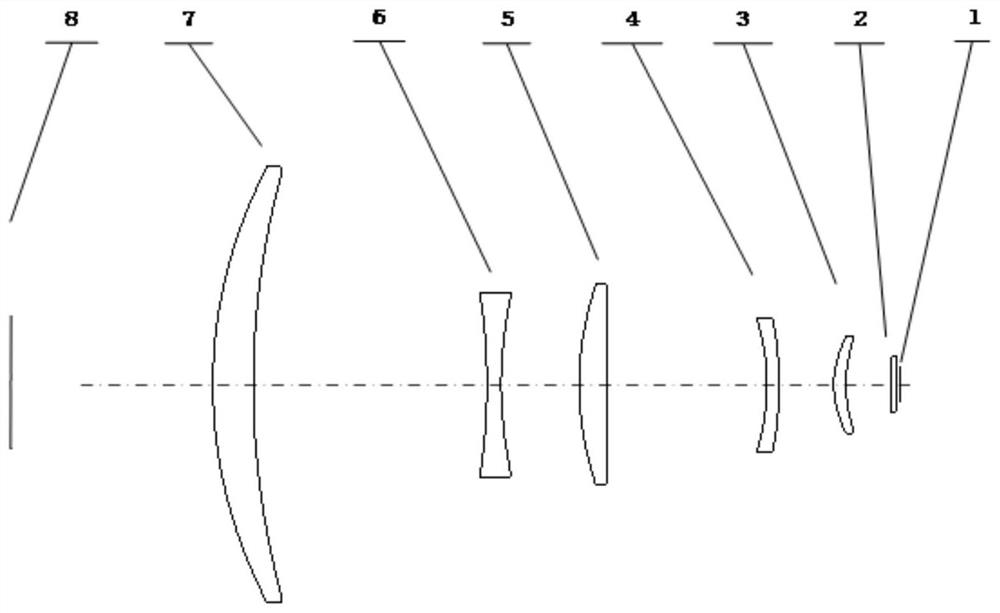
[0063] Various numerical data representing the zoom optical system involved in the first embodiment are as follows:

[0064] Focal length range: 25mm~150mm

[0065] Clear imaging range: 3m~INF

[0066] F / #=0.9~1.2, F# is the reciprocal of the ratio of the aperture of the entrance pupil to the focal length, that is, F=f / D

[0067] Optical total length: 150mm

[0068] Working spectrum range: 8μm~12μm

[0069] Detector to pin line size: 14mm

[0070] Heat dissipation temperature range: -45℃~+70℃

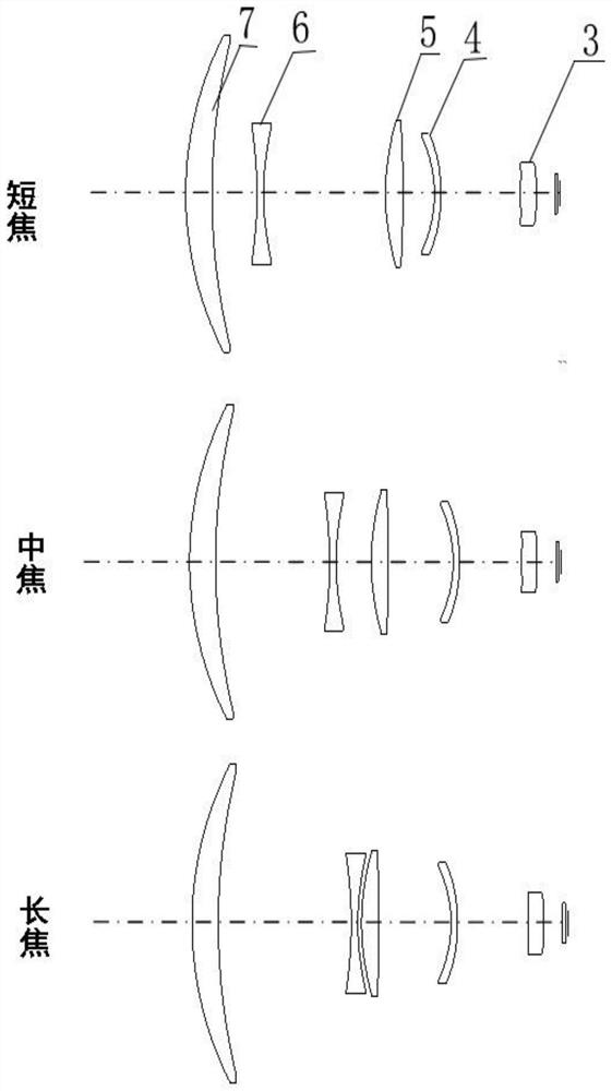
[0071] figure 2 It is a schematic diagram of the structure of the lens at different focal length positions according to the first embodiment of the present invention.

[0072] The following Table 1, Table 2 and Table 3 show various numerical values ​​related to the optical system involved in this embodiment.

[0073]

[0074]

[0075]

[0076] The total number of lenses in the optical system of this embodiment is small, and has better tolerance characteristics; the opti...

Embodiment 2

[0084] Various numerical data representing the zoom optical system involved in the second embodiment are as follows:

[0085] Focal length range: 25mm~200mm

[0086] Clear imaging range: 3m~INF

[0087] F / #=0.95~1.2

[0088] Optical total length: 200mm

[0089] Working spectrum range: 8μm~12μm

[0090] Detector to pin line size: 19.6mm

[0091] Heat dissipation temperature range: -45℃~+70℃

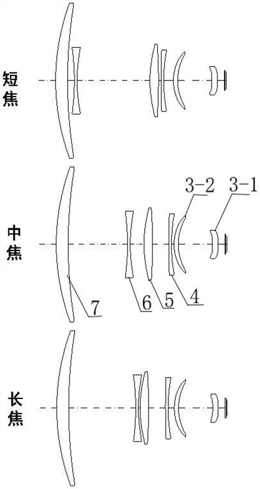
[0092] image 3It is a schematic diagram of the lens structure at different focal length positions in the second embodiment of the present invention.

[0093] The following Table 4, Table 5 and Table 6 show various numerical values ​​related to the optical system involved in this embodiment.

[0094]

[0095]

[0096]

[0097] In this embodiment, the total length from the surface of the front fixed lens group 7 close to the object plane 8 to the image plane 1 is 200 mm, the maximum diameter of each lens is less than 170 mm, the focal length ranges from 25 mm to 200 mm, and ...


PUM

PropertyMeasurementUnit
optical path lengthaaaaaaaaaa

Abstract

The invention belongs to the field of continuous zoom optical systems. Specifically, the invention discloses an uncooled long-wave infrared continuous zoom optical system. A front fixed lens group, a variable magnification lens group and a compensation lens are sequentially arranged along the optical axis from the object plane to the focal plane. The zoom lens group, the aberration stabilization lens group, the rear fixed lens group and the filter, the variable magnification lens group, the compensation lens group and the aberration stabilization lens group move linearly back and forth along the optical axis to realize continuous zooming, and the rear fixed lens group moves along the optical axis direction. Moving back and forth to achieve defocus compensation, the optical system of the present invention adopts a mechanical compensation zoom mode, and the zoom core is composed of a zoom group, a compensation group and an aberration stabilization lens group. Continuous zoom function with a magnification ratio of not less than 6 and a relative aperture of not more than 1.2. During the continuous change of the focal length, the central field of view and the edge field of view of all focal lengths have good imaging quality.

Description

technical field [0001] The invention belongs to the field of continuous zoom optical systems. Specifically, the present invention relates to a compact uncooled long-wave infrared continuous zoom optical system with a large relative aperture in the long-wave infrared band and capable of realizing continuous zoom function. Background technique [0002] With the cost reduction of uncooled long-wave infrared focal plane detectors, infrared thermal imager products with optical zoom function are more widely used, and the optical system as the core of this type of thermal imager needs to have optical zoom function. [0003] In the prior art, the long-wave infrared zoom optical system mainly has two implementations based on mechanical compensation and optical compensation. The optical compensation continuous zoom system realizes the continuous transformation of the field of view by moving two or more lens groups at the same speed. During the zooming process, the various components ...

Claims


Application Information

Patent Timeline
Patent Type & Authority Patents(China)
IPC IPC(8): G02B15/173
Inventor 许求真吴骏原高良陆贵兵
Owner KUNMING YUNZHE HIGH TECH
Why Eureka
Try Eureka