Imaging device provided with event-based camera

A camera device and event data technology, which is applied in the direction of cameras, focusing devices, installations, etc., can solve the problems of light dispersion of measurement objects and inability to accurately obtain event data, etc.

Active Publication Date: 2021-04-20
DENSO WAVE INC
View PDF10 Cites 2 Cited by
  • Summary
  • Abstract
  • Description
  • Claims
  • Application Information

AI Technical Summary

Problems solved by technology

Therefore, there is a problem that even with an event camera, if the measurement object is blurred and the li

Method used


Image

  • Imaging device provided with event-based camera
  • Imaging device provided with event-based camera
  • Imaging device provided with event-based camera

Examples


no. 1 approach

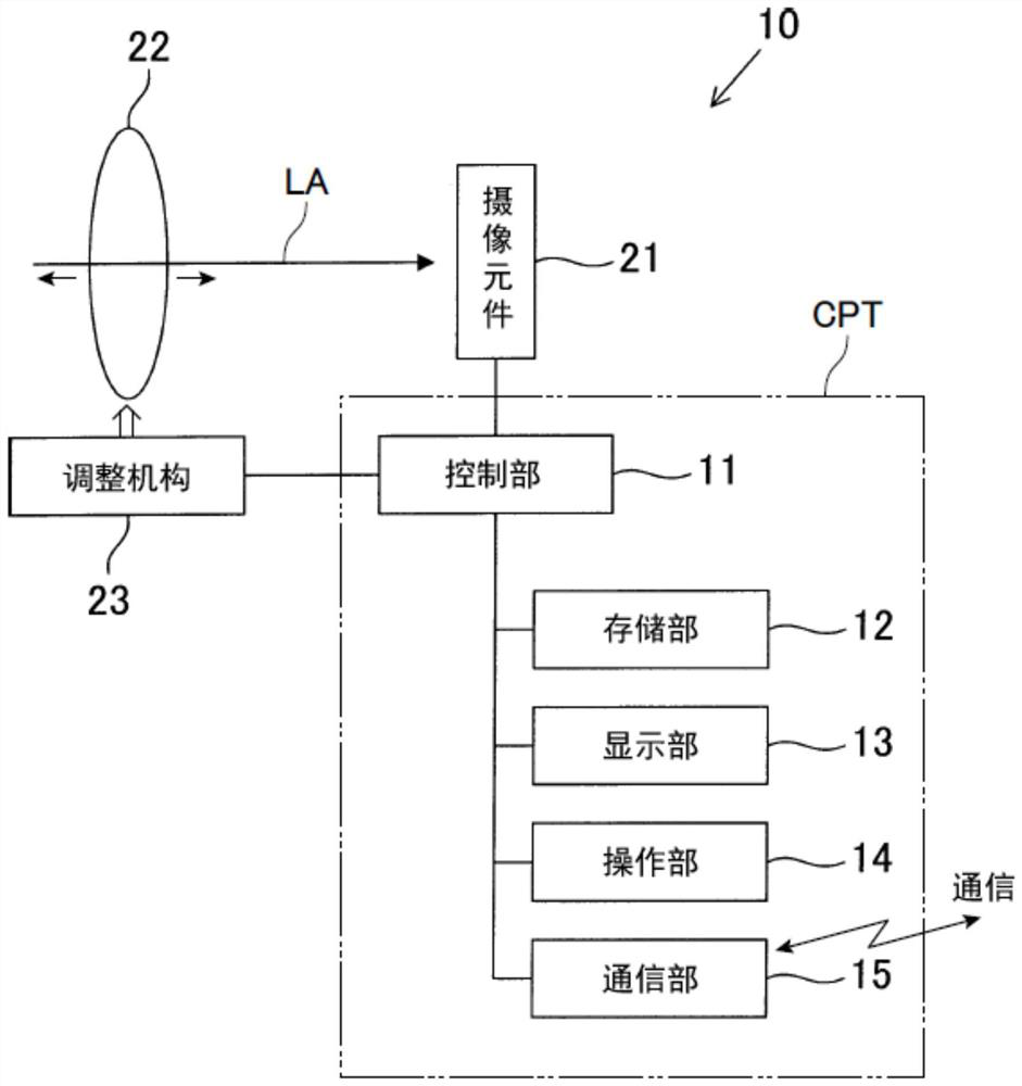
[0051] Below, refer to Figure 1 to Figure 6 , the first embodiment of the imaging device embodying the present invention will be described.

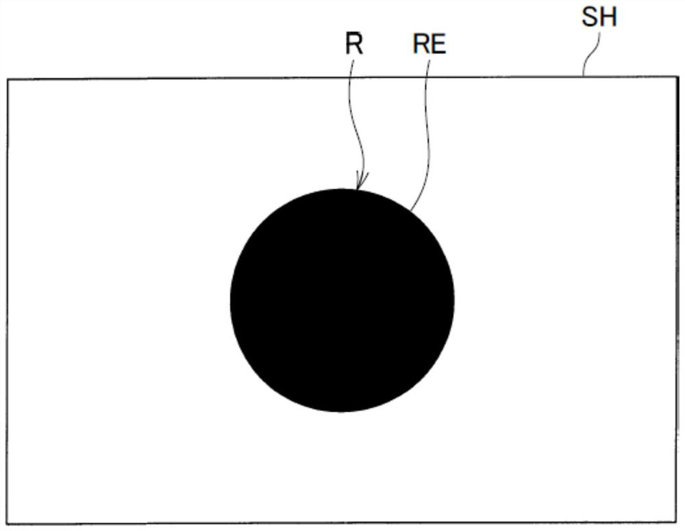
[0052] The imaging device 10 according to the present embodiment functions as a so-called event camera (Event Based Camera). This imaging device 10 is configured to detect event data including data for specifying the position of each pixel of a two-dimensional image having a brightness change, time, and the polarity (positive or negative) of the brightness change. Furthermore, this imaging device 10 is configured to create two-dimensional point data in which a plurality of event data outputted within a certain period of time are plotted on a given plane (predetermined plane), and to generate the two-dimensional point data as a photographed measurement image data of the object. In addition, the predetermined plane SH refers to a computationally two-dimensional plane set in the storage area of ​​the storage unit 12 described later, and ...

no. 2 approach

[0090] Below, refer to Figure 7 ~ Figure 8 , the second embodiment of the imaging device embodying the present invention will be described.

[0091] In this embodiment and subsequent embodiments, the same or equivalent constituent elements as those of the imaging device according to the first embodiment are given the same reference numerals, and descriptions thereof are simplified or omitted.

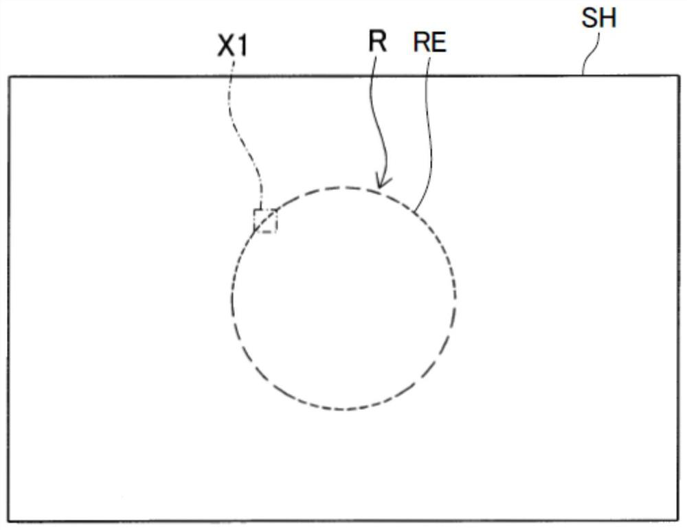
[0092] The imaging device 10A according to this embodiment is also a device that functions as a so-called event camera, similarly to the imaging device 10 described above. This imaging device 10 outputs event data in a polarity manner including two-dimensional point data PD, time, and polarity of luminance change, including two-dimensional point data PD that specifies the position of the pixel corresponding to a pixel having a luminance change, and outputs multiple data within a certain period of time. The two-dimensional point data PD of each event data is plotted as points on a pred...

no. 3 approach

[0105] Next, refer to Figure 9A , Figure 9B as well as Figure 10A ~ Figure 10D , the imaging device according to the third embodiment will be described.

[0106] The imaging device according to the third embodiment itself has the same configuration as the imaging device 10A according to the second embodiment.

[0107] The present third embodiment differs from the above-described second embodiment mainly in that the above-mentioned predetermined threshold value is changed in accordance with the amount of shift detected by the phase difference AF sensor 25 . Therefore, the same code|symbol is attached|subjected to the structural part which is substantially the same as 2nd Embodiment, and the description is abbreviate|omitted.

[0108] also, Figure 9A It is an explanatory diagram showing an example of the object to be measured, Figure 9B is the description received from the Figure 9A In the case of the light of the measurement object, the explanatory diagram of the ch...


PUM


Abstract

An imaging device in which an autofocus function can be performed without using brightness information is provided. In an imaging device according to one aspect, a density of points obtained by plotting two-dimensional point data of a plurality of event data (PD) as points on a plane (SH), the event data outputted from an imaging element (21) in a predetermined period in a state in which a focal point of a light receiving lens (22) is adjusted by an adjustment mechanism (23), is calculated as a point density. When the point density is calculated, a control unit (11) drives and controls the adjustment mechanism (23) based on comparison results between the point density currently calculated and the point density last calculated to thereby adjust the focal point toward the in-focus position. In another aspect, an imaging device having an autofocus function can be provided without using event data output from the imaging element.

Description

technical field [0001] The present invention relates to an imaging device including an optical system and an imaging element for optically imaging a subject, and particularly relates to an imaging device including an event camera (Event Based Camera). Background technique [0002] In recent years, an event camera disclosed in Patent Document 1 below has been known as a technique for generating an optical image of a measurement target at a higher speed. The event camera is a luminance value differential output camera inspired by the structure of the retina of a living being. It is configured to sense a change in luminance for each pixel and output its coordinates, time, and polarity of the change in luminance. [0003] According to this configuration, the event camera is characterized by not outputting redundant data, which is pixel information without luminance changes like conventional cameras, so it is possible to achieve higher speed by reducing the amount of data communi...

Claims


Application Information

Patent Timeline
IPC IPC(8): H04N5/232
CPCH04N23/67H04N23/672G02B7/34G03B13/36G03B19/12G02B7/09H04N23/959
Inventor 三谷勇介
Owner DENSO WAVE INC
Why Eureka
Try Eureka