Waste treatment equipment used for magnetic materials
What is AI technical title?
AI technical title is built by Patsnap AI team. It summarizes the technical point description of the patent document.
A technology for waste disposal and magnetic materials, which is applied in the direction of grain processing, etc., can solve the problems of magnetic material waste being pulled into and smashed, etc.
Inactive Publication Date: 2021-04-23
广州国智机电设备有限公司
View PDF0 Cites 2 Cited by
Summary
Abstract
Description
Claims
Application Information
AI Technical Summary
This helps you quickly interpret patents by identifying the three key elements:
Problems solved by technology
Method used
Benefits of technology
Problems solved by technology
[0003] Since the crushing roller inside the magnetic material waste grinder grinds the magnetic material waste through extrusion, if the magnetic material waste grinder grinds the spherical magnetic material waste with a smooth outer surface, two crushes are likely to occur. Rollers have difficulty pulling magnetic material waste into the shredder
Method used
Image
Click on the blue label to locate the original text in one second.
Reading with bidirectional positioning of images and text.
Examples
Embodiment 1
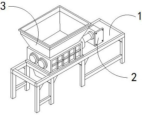
[0028] For example figure 1 -example Figure 5 Shown:
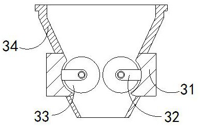
[0029] The present invention provides a kind of processing equipment for magnetic material waste, its structure includes laying a base and laying a base 1, a driver 2, and a crushing mechanism 3, the driver 2 is fixed on the right side of the crushing mechanism 3, and the bottom of the crushing mechanism 3 It is welded with the upper end of the base 1; the crushing mechanism 3 includes a shell 31, a fixed shaft 32, a crushing roller 33, and a feed hopper 34, and the rear end of the fixed shaft 32 is welded with the inner wall of the shell 31, and the crushed The middle part of the roller 33 is movably engaged with the front end of the fixed shaft 32 , and the bottom of the feeding hopper 34 is connected with the upper end of the casing 31 .
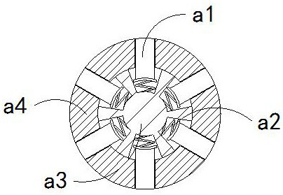
[0030] Wherein, the crushing roller 33 includes an outreach rod a1, a rebound bar a2, a middle block a3, and a circumscribed ring a4. Between the rear end of the outrigger a1 and ...
Embodiment 2
[0036] For example Figure 6 -example Figure 9 Shown:
[0037] Wherein, the receiving plate b2 includes an outer pushing block b21, a connecting plate b22, and an inner fixing plate b23. The inner wall of the plate b22 is embedded and connected. There are four pusher blocks b21, and two of them are evenly distributed in an arc on the inner side of the joint plate b22. The pushing block b21 slides outward along the inner solid plate b23.
[0038]Wherein, the extrapolation block b21 includes an outer ring c1, a slotted block c2, a reset piece c3, and an engaging block c4, the slotted block c2 is slidingly matched with the inside of the outer ring c1, and the reset piece c3 is installed on Between the slotted block c2 and the inner wall of the outer ring c1, the connecting block c4 is installed at the inner center of the outer ring c1, and there are four slotted blocks c2, which are uniformly inside the outer ring c1 Distributed in a circular shape, the slotted block c2 can ...
PUM
Abstract
The invention discloses waste treatment equipment used for magnetic materials. The waste treatment equipment structurally comprises a base, a driver and a smashing mechanism. The driver is fixed to the right side position of the smashing mechanism, and the bottom of the smashing mechanism and the upper end of the base are welded. Through throwing force generated by rotating, driving blocks can slide outwards and extend out along the plate surface under the cooperation of linkage rods, and therefore the driving blocks can drive spherical magnetic material waste, outer pushing blocks can slide outwards and extend out along inner fixed plates through inertia force generated by outward extending of the driving blocks, then through throwing force generated by rotation of the outer pushing blocks, grooving blocks can slide outwards and extend out along external rings, and therefore the grooving blocks can hit the outer surfaces of the spherical magnetic material waste out of grooves, and two smashing rollers can smoothly smash the spherical magnetic material waste which is large in size and extremely smooth in surface.
Description
technical field [0001] The invention relates to the field of magnetic materials, in particular to a processing device for magnetic material waste. Background technique [0002] The magnetic material waste grinder is mainly used for crushing magnetic material waste. By pouring the magnetic material waste into the magnetic material waste grinder, the magnetic material is crushed by two high-speed rotating grinding rollers inside the magnetic material waste grinder. The waste is crushed and processed. Based on the above description, the inventors have found that the existing magnetic material waste treatment equipment mainly has the following deficiencies, such as: [0003] Since the crushing roller inside the magnetic material waste grinder grinds the magnetic material waste through extrusion, if the magnetic material waste grinder grinds the spherical magnetic material waste with a smooth outer surface, two crushes are likely to occur. It is difficult for the rollers to pull...
Claims
Application Information
Patent Timeline
Application Date:The date an application was filed.
Publication Date:The date a patent or application was officially published.
First Publication Date:The earliest publication date of a patent with the same application number.
Issue Date:Publication date of the patent grant document.
PCT Entry Date:The Entry date of PCT National Phase.
Estimated Expiry Date:The statutory expiry date of a patent right according to the Patent Law, and it is the longest term of protection that the patent right can achieve without the termination of the patent right due to other reasons(Term extension factor has been taken into account ).
Invalid Date:Actual expiry date is based on effective date or publication date of legal transaction data of invalid patent.

