Plastic production equipment

A technology for production equipment and plastics, which is applied in the field of plastics, and can solve the problems of reduced crushing effect of plastic shredders and difficulty in crushing, etc.

Inactive Publication Date: 2020-07-28
陈倩倩
View PDF4 Cites 5 Cited by
  • Summary
  • Abstract
  • Description
  • Claims
  • Application Information

AI Technical Summary

Problems solved by technology

[0003] Since the plastic pulverizer grinds the plastic raw material through the rotation of the internal agitating knife, and the polyethylene plastic has strong elasticity and soft texture, so that it is not easy for the plastic pulverizer to pulverize the spherical polyethylene plastic, which causes the plastic pulverizer to be damaged. Its crushing effect is reduced

Method used


Image

  • Plastic production equipment
  • Plastic production equipment
  • Plastic production equipment

Examples


Embodiment 1

[0027] For example figure 1 -example Figure 5 Shown:

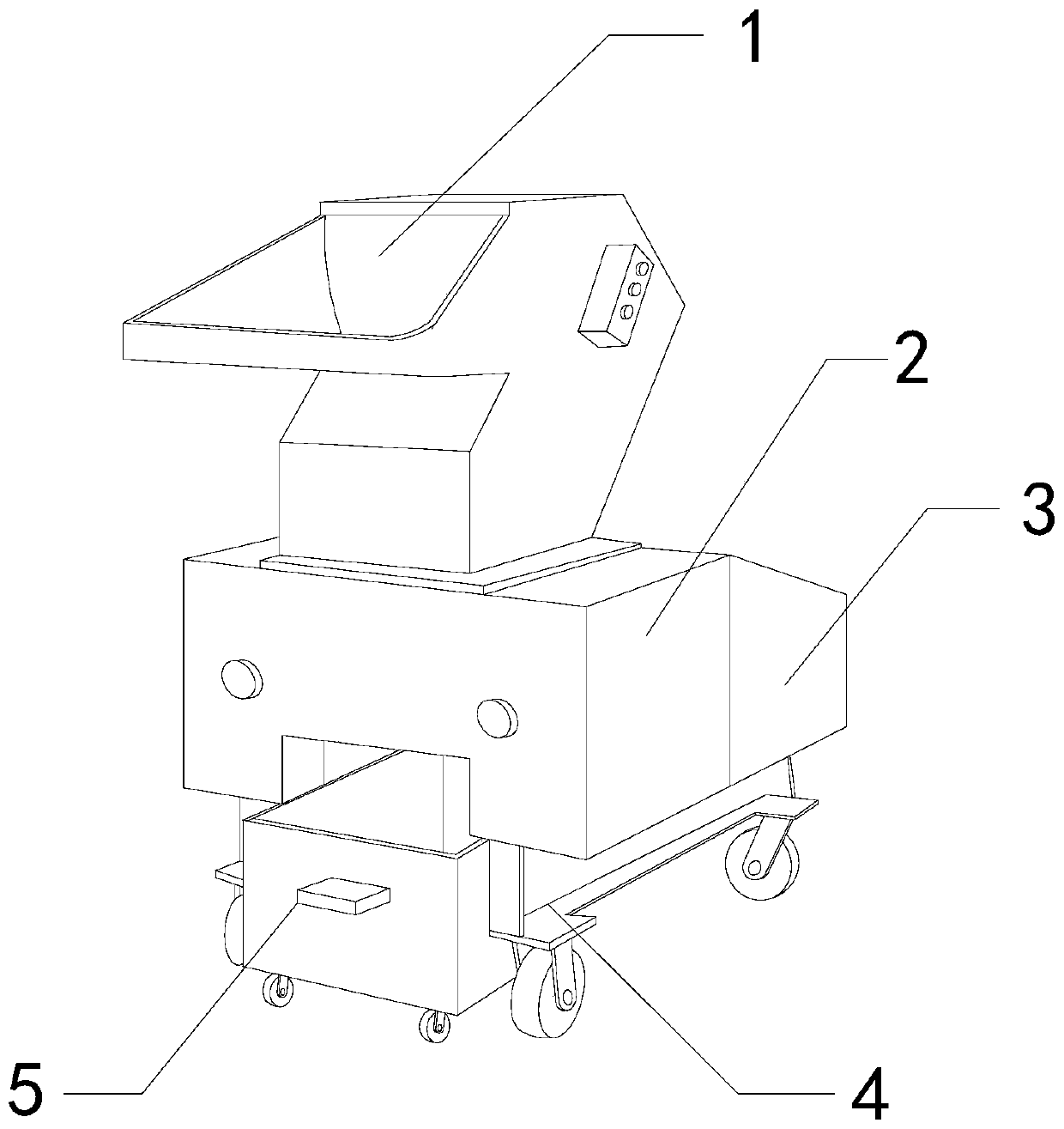
[0028] The present invention provides a kind of plastic production equipment, its structure comprises feeding hopper 1, crushing bin 2, power bin 3, base support 4, collecting bucket 5, described power bin 3 is installed in the back end position of crushing bin 2, and described base The bracket 4 is embedded and fixed at the lower end of the crushing bin 2 , the collecting bucket 5 is in clearance fit with the base bracket 4 , and the crushing bin 2 is welded at the lower end of the feeding hopper 1 .

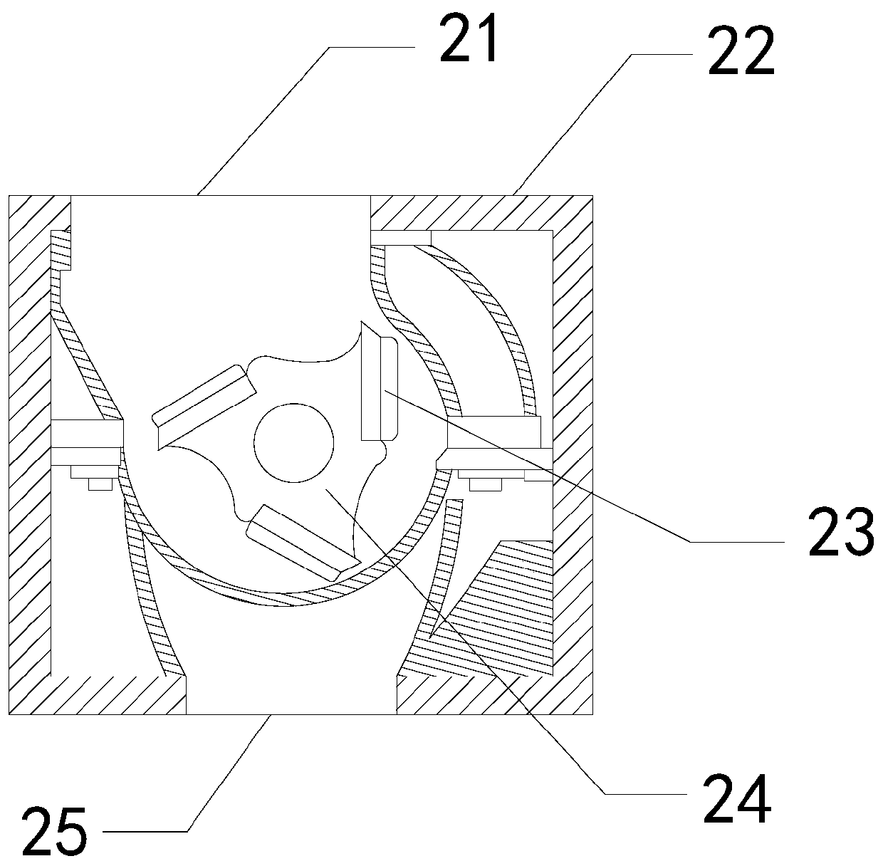
[0029] Wherein, the crushing bin 2 includes an inlet 21, a casing 22, a crushing cutter 23, a rotating block 24, and a discharge port 25. The inlet 21 and the casing 22 are an integrated structure, and the crushing cutter 23 is embedded in the rotating block 24. The position of the outer surface of the rotating block 24 is movably engaged with the inner position of the casing 22, the discharge port 25 is installed at the...

Embodiment 2

[0036] For example Figure 6 -example Figure 8 Shown:

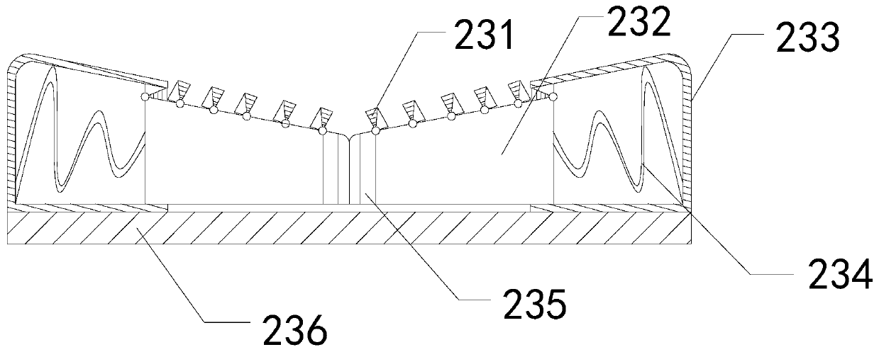
[0037] Wherein, the crushing mechanism 231 includes a movable plate b1, a rotating wheel b2, a cleaning block b3, a cutter head b4, a connecting rod b5, and a movable groove b6. The movable wheel b2 is movably engaged with the movable plate b1, and the cleaning block b3 The gap fits between two adjacent connecting rods b5, the cutter head b4 is welded to the bottom position of the connecting rod b5, the connecting rod b5 and the movable plate b1 are an integrated structure, and the movable groove b6 is installed on the corresponding Between the two adjacent connecting rods b5, the cutter head b4 on the connecting rod b5 can cut the spherical polyethylene plastic with smaller volume, and the movable groove b6 is filled with polyether sponge with stronger resilience, The removal block b3 can be pushed to remove the spherical polyethylene plastic cut by the cutter head b4.

[0038] Wherein, the cutter head b4 includes an...


PUM


Abstract

The invention discloses plastic production equipment. The plastic production equipment structurally comprises a feeding hopper, a crushing bin, a power bin, a base support, and a collection hopper; the power bin is installed at the rear end of the crushing bin; the base support is embedded in and fixed at the lower end of the crushing bin; the collection hopper is in clearance fit with the base support; the crushing bin is welded to the lower end of the feeding hopper; through the cooperation of a rotating block in the crushing bin and a crushing tool, spherical polyethylene plastic can be crushed, a cutting blade is driven by a movable bending rod to cut the polyethylene plastic to avoid the condition that the polyethylene plastic is not likely to be crushed by the crushing tool, a crushing mechanism on a telescopic block can crush the spherical polyethylene plastic with smaller size, and a tool bit on a connecting rod can cut the spherical polyethylene plastic of which the bottom issmaller to avoid the condition that a cutting mechanism cannot crush spherical polyethylene plastic with smaller size.

Description

technical field [0001] The invention relates to the field of plastics, in particular to a plastic production equipment. Background technique [0002] The plastic pulverizer is mainly used to crush plastic raw materials. It can pulverize large plastic raw materials into granules by stirring, so as to be heated into molten plastic. It is a necessary link in the processing and molding of plastic products. Based on the above description The inventors found that the existing plastic production equipment mainly has the following deficiencies, such as: [0003] Since the plastic pulverizer grinds the plastic raw material through the rotation of the internal agitating knife, and the polyethylene plastic has strong elasticity and soft texture, so that it is not easy for the plastic pulverizer to pulverize the spherical polyethylene plastic, which causes the plastic pulverizer to be damaged. Its crushing effect is reduced. Contents of the invention [0004] In view of the above pr...

Claims


Application Information

Patent Timeline
IPC IPC(8): B29B13/10B02C18/14B02C18/18B02C18/16
CPCB02C18/14B02C18/16B02C18/18B29B13/10
Inventor 陈倩倩
Owner 陈倩倩
Why Eureka
Try Eureka