Method and device for realizing square wave quadrature demodulation of closed-loop resonant optical gyroscope

A quadrature demodulation and optical gyroscope technology, applied in the fields of optical sensing and signal detection, can solve problems such as phase fluctuation of the square wave signal to be demodulated, and achieve the effects of suppressing demodulation signal fluctuation, suppressing performance degradation, and improving accuracy

Active Publication Date: 2021-04-23
ZHEJIANG UNIV
View PDF3 Cites 4 Cited by
  • Summary
  • Abstract
  • Description
  • Claims
  • Application Information

AI Technical Summary

Problems solved by technology

[0007] Aiming at the phase fluctuation problem of the square wave signal to be demodulated due to the change of environmental factors such as temperature in the closed-loop resonant optical gyroscope system, the present invention proposes a method and device for realizing square wave quadrature demodulation of the closed-loop resonant optical gyroscope

Method used


Image

  • Method and device for realizing square wave quadrature demodulation of closed-loop resonant optical gyroscope
  • Method and device for realizing square wave quadrature demodulation of closed-loop resonant optical gyroscope
  • Method and device for realizing square wave quadrature demodulation of closed-loop resonant optical gyroscope

Examples


Embodiment 1

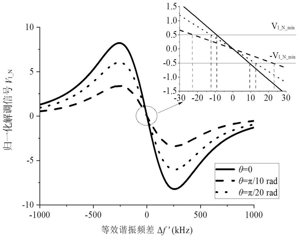
[0093] Figure 9 This is the test result of the demodulation curve before and after square wave quadrature demodulation. The demodulation curve is obtained by scanning the center frequency of the laser. Figure 9 (a) is the demodulation curve without square wave quadrature demodulation; Figure 9 (b) is the demodulation curve under square wave quadrature demodulation, its working point θ 0 Set to π / 4rad. In the experiment, artificially set Δθ to 0, π / 20rad and π / 10rad. It can be found that when square wave quadrature demodulation is not used, such as Figure 9 As shown in (a), the slope of the demodulation curve will fluctuate with Δθ, so it is impossible to keep the slope of the demodulation curve at the maximum value; when the square wave quadrature demodulation method is adopted, as Figure 9 As shown in (b), the slope fluctuation of the demodulation curve is suppressed and almost kept near the maximum value.

Embodiment 2

[0095] To illustrate the necessity of optimizing the phase operating point when using square wave quadrature demodulation, Figure 10 The demodulation curve test comparison results when the operating point is set to 0 and π / 4rad are given. It can be found that when the operating point is set to 0, there is an obvious fluctuation around the resonance point, and when the operating point is set to π / 4rad, the fluctuation is suppressed.

Embodiment 3

[0097] Figure 11 The Allan variance analysis results of the test data of the gyroscope 1h output signal when the square wave quadrature demodulation method is used and the working points are set to 0 and π / 4rad respectively are given. The integration time is 0.1s and the sampling rate is 10Hz. according to Figure 11 According to the Allan variance analysis results, when the quadrature demodulation operating point is set to 0, the zero bias stability of about 11.9deg / h can be obtained, which is even better than what we have reported Figure 12 The test result shown without the square wave quadrature demodulation scheme is worse at about 7.1deg / h, which may be caused by the demodulation curve fluctuating near the resonance point under the non-ideal phase operating point. However, when the operating point is set to π / 4rad, a bias stability of about 6.0deg / h can be obtained. The bias stability is about Figure 12 The non-square-wave quadrature demodulation scheme shown yield...


PUM


Abstract

The invention discloses a method and a device for realizing square wave quadrature demodulation of a closed-loop resonant optical gyroscope, and belongs to the technical field of optical sensing and signal detection. A photoelectric detector is used for detecting light output by an optical resonant cavity, then orthogonal demodulation is conducted on signals output by the photoelectric detector through a square wave orthogonal demodulation module, and orthogonal demodulation signals are obtained; wherein the square wave quadrature demodulation module comprises two channels, and in the first channel, a signal output by the photoelectric detector obtains a first demodulation signal according to a first channel reference signal; in the second channel, the signal output by the photoelectric detector obtains a second demodulation signal according to a second channel reference signal; and obtaining a finally output square wave quadrature demodulation signal according to the difference between the first demodulation signal and the second demodulation signal. According to the invention, the problem that the performance of the closed-loop resonant optical gyro system is reduced due to the phase fluctuation of the square wave signal can be effectively inhibited, and the precision of the optical gyro is improved.

Description

technical field [0001] The invention relates to the technical field of optical sensing and signal detection, in particular to a method and device for realizing square wave quadrature demodulation of a closed-loop resonant optical gyroscope. [0002] technical background [0003] The resonant optical gyroscope is a rotational angular velocity measurement sensor based on the Sagnac effect and with an optical ring resonant cavity as the core sensitive element. [0004] Phase modulation and demodulation technology can be used for resonant optical gyroscope signal detection, and this technology has been widely used in resonant optical gyroscope systems. In order to improve the accuracy of the resonant optical gyro system, a method of phase modulation and demodulation using various modulation waveforms has been proposed and applied to the resonant optical gyro system, including sine wave modulation, triangular wave modulation, and sawtooth wave modulation. modulation etc. In an a...

Claims


Application Information

Patent Timeline
Patent Type & Authority Applications(China)
IPC IPC(8): G01C19/66
CPCG01C19/66G01C19/661G01C19/667
Inventor 应迪清刘强王泽宇谢涛金仲和
Owner ZHEJIANG UNIV
Why Eureka
Try Eureka