
Filling material having strips with asymmetrical arch or wave shapes

A technology of arched shape and strips, applied in chemical/physical/physicochemical processes, chemical instruments and methods, chemical/physical processes, etc., can solve problems such as damaged separation performance, achieve distribution improvement, good interruption, Avoid Overlapping Effects

Inactive Publication Date: 2021-04-23
RVT PROCESS EQUIP
View PDF7 Cites 1 Cited by
  • Summary
  • Abstract
  • Description
  • Claims
  • Application Information

AI Technical Summary

Problems solved by technology

[0006] A disadvantage of this packing element is that, seen along the curved longitudinal axis of the packing element, the individual ribs at least partially overlap
In this orientation, therefore, the packing elements have a very large open cross-section, which can lead to disadvantages such as the formation of liquid ducts and thus to impaired separation properties

Method used


Image

  • Filling material having strips with asymmetrical arch or wave shapes
  • Filling material having strips with asymmetrical arch or wave shapes
  • Filling material having strips with asymmetrical arch or wave shapes

Examples


Embodiment Construction

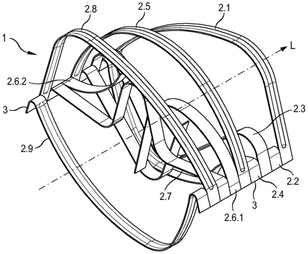
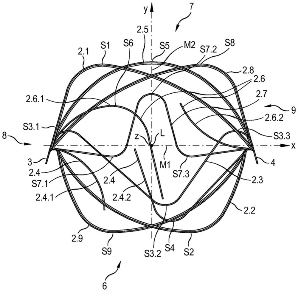
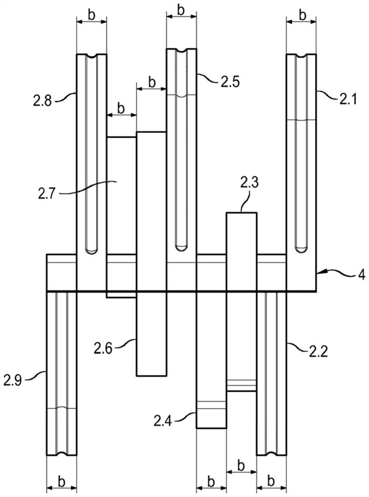
[0035]infigure 1 In a perspective view, a filler element in accordance with the present invention is shown. The filler element 1 includes a plurality of adjacent strips 2.1, 2.2, 2.3, 2.4, 2.5, 2.2, 2.7, 2.8, 2.9, in the illustrated embodiment. The strips 2.2, 2.2, 2.3, 2.4, 2.5, 2.6, 2.7, 2.8, 2.9 from the first middle plane M1 of the filler element 1 (seefigure 2 ) Begins to be bent outward and thus determines the volume of the filler element 1. The strip is a strip (sheet shape) having a width B and the length L. The exact shape of the strips 2.2, 2.2, 2.3, 2.4, 2.5, 2.6, 2.7, 2.8, 2.9 will be described in more detail with reference to the following drawings.

[0036]Preferably, all of the strings have the same width B, and the width is 5 mm in the illustrated embodiment, however, at least some of the strips have different widths will also be possible. The length L of all strings is equal. At the two edges of the filler element 1, a lateral web 3, 4 is formed parallel to the longitu...


PUM


Abstract

The invention relates to a filling material, in particular for material and / or heat exchange columns, through which at least one gas and / or at least one liquid flow flows, comprising a plurality of strips arranged next to one another and curved inwards and / or outwards, wherein each strip is connected to the neighbouring strips at at least one end thereof. The object of the invention is to provide a filling material that is improved relative to the state of the art. According to the invention, this is achieved in that at least one of the strips has an irregular shape.

Description

Technical field[0001]This patent application relates to a filler element, particularly a filler element for mass exchange columns and / or heat exchange columns, at least one gas, and / or at least one liquid flow through the filler element, which includes each other side by side and Multiple strips of inward and / or outward, each of which is coupled to adjacent one or more strips at least one end of the strip.Background technique[0002]Such a filler element has been known for a long time and is applied, for example, to the mass transfer and / or heat transfer process in the tower or chemical reactor. For example, these random filler elements referred to as stacked filler elements are applied to gas-liquid contact instruments or liquid-liquid contact instruments to flow downward flowing fluids typically a liquid flow or A mass transfer surface is formed between the steam stream or the upward fluid of the other liquid stream.[0003]Unregulated filler elements are applied to multiple c...

Claims


Application Information

Patent Timeline
IPC IPC(8): B01J19/30
CPCB01J19/30B01J2219/30203B01J2219/30296B01J2219/30223B01J2219/30288B01J2219/30276
Inventor 维尔纳·盖佩尔克里斯蒂安·盖佩尔克里斯蒂安·梅林格卡琳·霍夫曼
Owner RVT PROCESS EQUIP
Learn More