Anti-seepage short wall simulation device for controlling breakwater foundation piping development and test method thereof

A technology of simulating device and base pipe, which is applied in the field of seepage control of embankment foundation, and can solve the problems such as the damage of anti-seepage wall to control pipe surge and so on.

Active Publication Date: 2021-04-27
CHINA INST OF WATER RESOURCES & HYDROPOWER RES
View PDF6 Cites 7 Cited by
  • Summary
  • Abstract
  • Description
  • Claims
  • Application Information

AI Technical Summary

Problems solved by technology

[0004] The above method only understands the development process of piping through indirect detection, and cannot directly observe the formation and development of embankment damage when the upstream water head changes, and when there is a cut-off wall in the embankment foundation, the cut-off wall cannot be directly observed. Influence on controlling piping damage

Method used


Image

  • Anti-seepage short wall simulation device for controlling breakwater foundation piping development and test method thereof
  • Anti-seepage short wall simulation device for controlling breakwater foundation piping development and test method thereof
  • Anti-seepage short wall simulation device for controlling breakwater foundation piping development and test method thereof

Examples


Embodiment 1

[0080] The test method for the short-wall simulator to control the development of embankment piping includes the following steps:

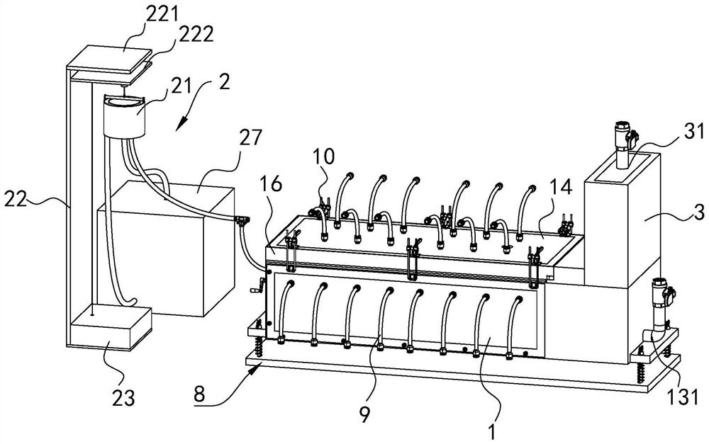
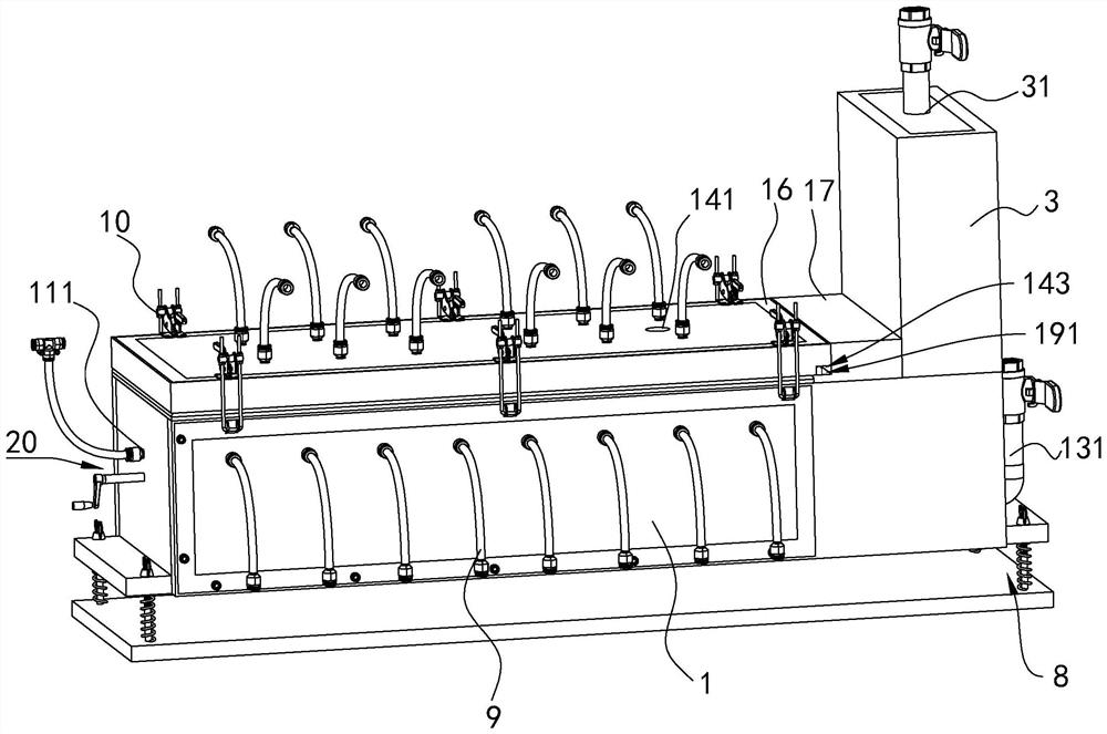
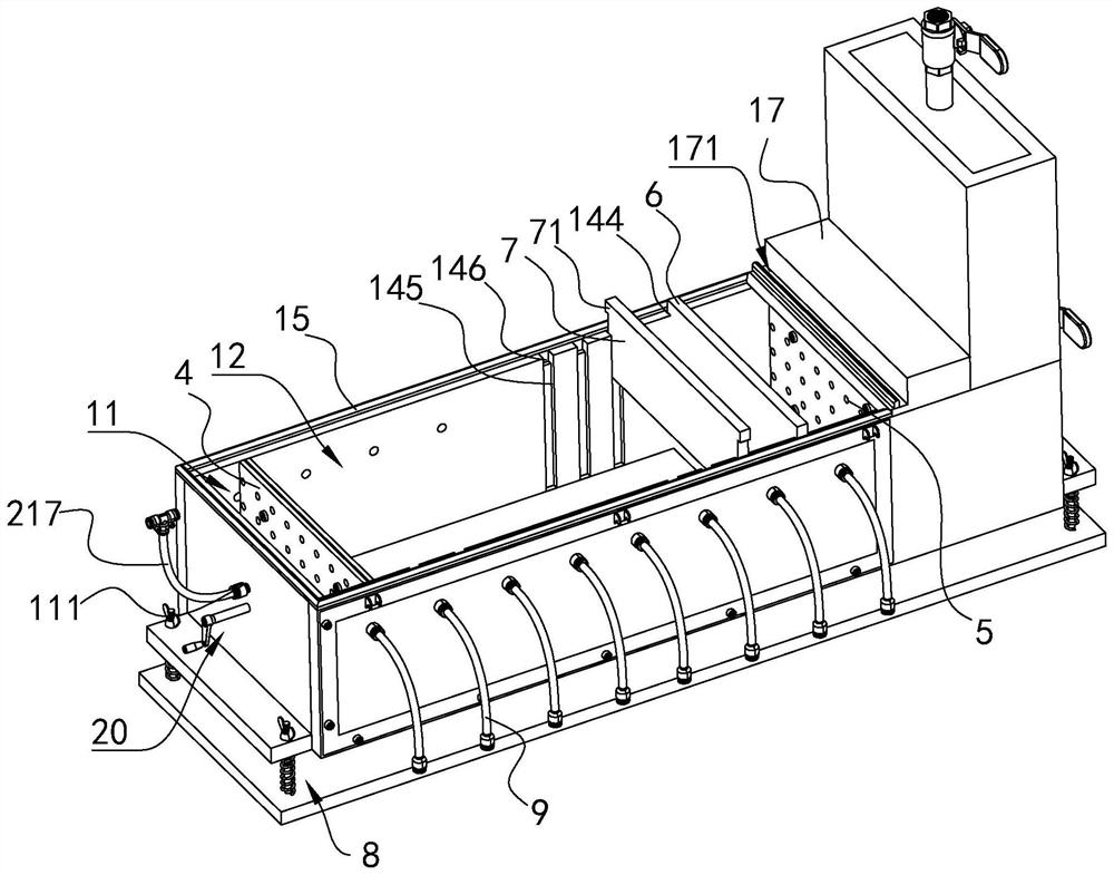
[0081] S1. According to the determined infiltration path length, the first infiltration assembly 4 is moved to the design position by the propulsion mechanism 20, and the anti-seepage short wall 7 is inserted into the second slot 145 according to the set penetration degree and position, and then to the second slot 145. The sand sample filling chamber 12 between the first diafiltration assembly 4 and the second diafiltration assembly 5 is filled with sand samples.

[0082] Sand samples can be filled with single-layer sand samples, double-layer sand samples or three-layer sand samples according to the test requirements to simulate single-layer embankment foundations, double-layer embankment foundations or three-layer embankment foundations.

[0083] The filling of the sand sample is carried out by layered underwater throwing, scraping and compacting...

Embodiment 2

[0094] The test method for the short-wall simulator to control the development of embankment piping includes the following steps:

[0095] S1. According to the determined infiltration path length, the first infiltration assembly 4 is moved to the design position by the propulsion mechanism 20, and the partition plate 6 is inserted into the first slot 144, and the anti-seepage short wall 7 is set according to the penetration degree and the position is inserted into the second slot 145, and then the sand sample is filled between the first infiltration assembly 4 and the partition 6.

[0096] Sand samples can be filled with single-layer sand samples, double-layer sand samples or three-layer sand samples according to the test requirements to simulate single-layer embankment foundations, double-layer embankment foundations or three-layer embankment foundations.

[0097] The filling of the sand sample is carried out by layered underwater throwing, scraping and compacting, each layer...


PUM


Abstract

The invention relates to an anti-seepage short wall simulation device for controlling breakwater foundation piping development and a test method thereof, and belongs to the field of breakwater foundation seepage control. The device comprises a sand tank box, an upstream water level control system, and a data acquisition system for monitoring a test process; a first percolation assembly for dividing the sand tank box into an upstream water inlet chamber and a sand sample filling chamber is arranged in the sand tank box; the top end of the sand tank box is sealed by a detachable cover plate; a piping hole penetrating through the cover plate is formed in the bottom surface, located in the sand sample filling chamber, of the cover plate; an anti-seepage short wall is arranged between the first percolation assembly and the piping hole; the anti-seepage short wall is designed to be provided with various penetration degrees and positions; and side plates and the cover plate of the sand tank box are made of colorless transparent materials. According to the anti-seepage short wall simulation device for controlling breakwater foundation piping development and the test method thereof, the formation and development process of breakwater foundation piping can be visually observed, different control piping development processes under the condition of the anti-seepage short walls with different penetration degrees and positions can be visually observed, and the situation is compared with a piping damage situation under the condition of no anti-seepage short walls.

Description

technical field [0001] The present application relates to the field of dike foundation seepage control, in particular to a short seepage-proof short wall simulation device for controlling the development of dike foundation piping and a test method thereof. Background technique [0002] Dike foundation piping means that under the action of the difference in water head inside and outside the embankment, seepage inside the embankment penetrates the downstream topsoil layer, and seepage outlets, namely piping outlets, appear. A sand ring is formed at the orifice, and a seepage channel is formed inside the embankment along the contact surface between the embankment sand layer and the bottom of the embankment or the topsoil covering layer of the embankment body. As the water head increases, the channel develops back upstream to form a tubular seepage channel , and transport sand from the channel to the downstream seepage outlet. When a certain water head is reached, the piping ch...

Claims


Application Information

Patent Timeline
Patent Type & Authority Applications(China)
IPC IPC(8): E02B1/02E02B3/16
CPCE02B1/02E02B3/16
Inventor 丁留谦姚秋玲刘昌军张启义张顺福翟晓燕解家毕
Owner CHINA INST OF WATER RESOURCES & HYDROPOWER RES
Why Eureka
Try Eureka