Micro-hole wall imaging equipment

An imaging device and technology of tiny holes, applied in optical components, optics, instruments, etc., can solve the problems of difficult operation, unguaranteed reliability and consistency, and unclear imaging of the inner wall of the hole.

Active Publication Date: 2021-04-27
苏州聚悦信息科技有限公司
View PDF6 Cites 0 Cited by
  • Summary
  • Abstract
  • Description
  • Claims
  • Application Information

AI Technical Summary

Problems solved by technology

[0003] However, the existing technology center lacks primary imaging equipment and systems for large depth-of-field micro-hole walls, so the existing equipment systems cannot image the inner walls of the holes clearly, and the illumination is not enough. At the same time, the 360-degree primary imaging of the hole walls needs to go deep into the hole and rotate a circle. The structure is complex and difficult to operate, and the defects of the inner hole wall rely on manual supplementation, and the reliability consistency cannot be guaranteed

Method used


Image

  • Micro-hole wall imaging equipment
  • Micro-hole wall imaging equipment
  • Micro-hole wall imaging equipment

Examples


Embodiment Construction

[0019] The following will clearly and completely describe the technical solutions in the embodiments of the present invention with reference to the accompanying drawings in the embodiments of the present invention. Obviously, the described embodiments are only some, not all, embodiments of the present invention.

[0020] In describing the present invention, it should be understood that the terms "upper", "lower", "front", "rear", "left", "right", "top", "bottom", "inner", " The orientation or positional relationship indicated by "outside", etc. is based on the orientation or positional relationship shown in the drawings, and is only for the convenience of describing the present invention and simplifying the description, rather than indicating or implying that the referred device or element must have a specific orientation, so as to Specific orientation configurations and operations, therefore, are not to be construed as limitations on the invention.

[0021] refer to Figure ...


PUM


Abstract

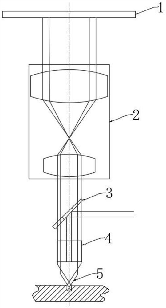
The invention discloses micro-hole wall imaging equipment. The equipment comprises an inclined composite mirror; a light guide mirror is fixedly installed under the composite mirror; a reflector is fixedly connected to the lower portion of the light guide mirror; an image zooming module is fixedly installed over the composite mirror; a CCD imaging module is fixedly installed over the image zooming module; the image zooming module comprises two convex lenses which are placed along the same vertical axis and are different in size. A light reflecting mirror, the light guide mirror, the reflector, the image zooming module, the CCD imaging module and the like are adopted, a clear image of a micro hole wall can be obtained; an illumination light path is separated from an imaging light path, so that the influence of stray light is avoided, the definition of the hole wall image is improved; and meanwhile, the light explosion phenomenon can be avoided through the unique design of the light reflecting mirror; and finally, clear imaging is carried out on the interior of a micro hole.

Description

technical field [0001] The invention relates to the technical field of optical imaging equipment, in particular to micro-hole wall imaging equipment. Background technique [0002] In the process of workpiece processing and inspection, it is often necessary to detect the information of the groove or the inner wall of the hole to ensure the pass rate of the workpiece processing. However, due to the shape or size of the workpiece itself, it is sometimes difficult to directly detect the hole Or slotted information usually requires the use of microscopic hole wall imaging equipment. [0003] However, the existing technology center lacks primary imaging equipment and systems for large depth-of-field micro-hole walls, so the existing equipment systems cannot image the inner walls of the holes clearly, and the illumination is not enough. At the same time, the 360-degree primary imaging of the hole walls needs to go deep into the hole and rotate a circle. The structure is complex an...

Claims


Application Information

Patent Timeline
Patent Type & Authority Applications(China)
IPC IPC(8): G02B17/02
CPCF21V13/12G02B17/08
Inventor 刘金建郭鸿飞张程黄新龙随岁寒
Owner 苏州聚悦信息科技有限公司
Why Eureka
Try Eureka