A floor tile gap cleaning device

A technology for cleaning devices and gaps, used in carpet cleaning, floor cleaning, cleaning machinery, etc., can solve the problems of slow cleaning speed, troublesome operation, loud noise, etc., and achieve the effect of ensuring the cleaning effect.

Active Publication Date: 2022-04-22
创际建工集团有限公司
View PDF0 Cites 0 Cited by
  • Summary
  • Abstract
  • Description
  • Claims
  • Application Information

AI Technical Summary

Problems solved by technology

The decorative effect of beautiful seams is relatively strong. It can not only enhance the overall sense of luxury of the tiles, but also help to clean the tiles, because there are gaps when laying tiles, and debris will fall into the gaps. Don't worry about this problem. During the construction of beautiful joints, workers use vacuum cleaners to clean the gaps between tiles. This method is slow in cleaning speed, loud in the cleaning process, and poor in cleaning effect. It also requires manual alignment of the suction tube of the vacuum cleaner. Gap and move, troublesome to operate

Method used


Image

  • A floor tile gap cleaning device
  • A floor tile gap cleaning device
  • A floor tile gap cleaning device

Examples


specific Embodiment approach 1

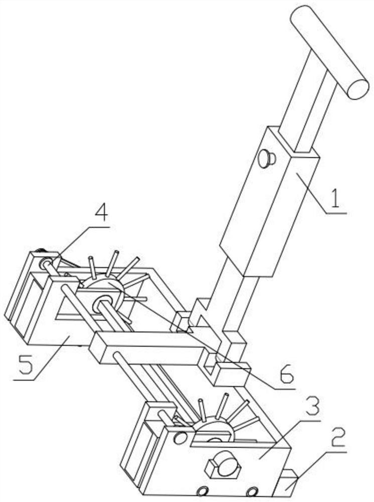
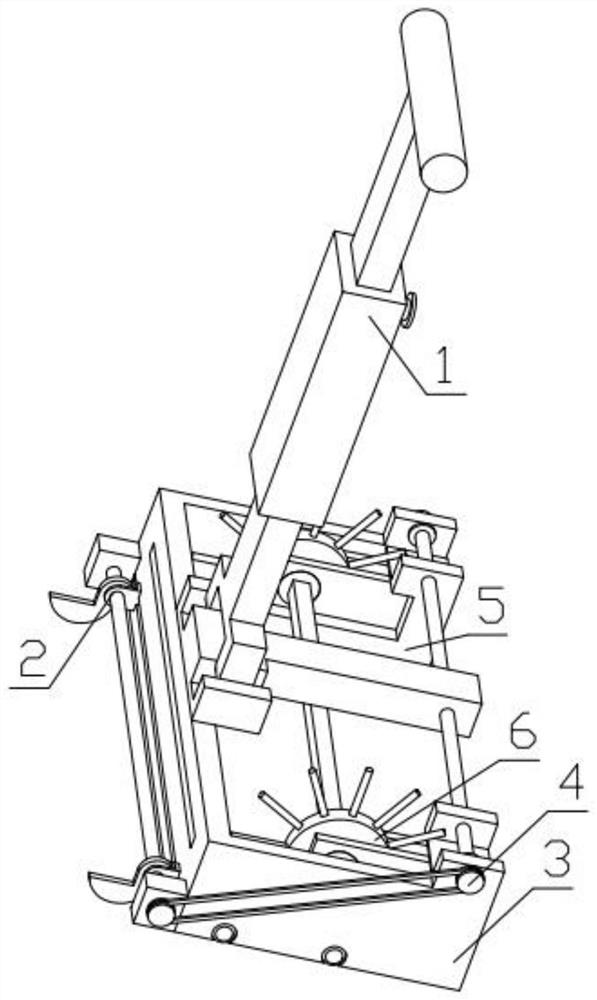
[0036] Combine below Figure 1-16 Describe this embodiment, a floor tile gap cleaning device, including a telescopic handle 1, a limit mechanism 2, a U-shaped frame 3, a synchronous adjustment mechanism 4, a collection box 5 and a cleaning mechanism 6, and the limit mechanism 2 is fixedly installed On the U-shaped frame 3, the U-shaped frame 3 is hinged with the telescopic handle 1, the synchronous adjustment mechanism 4 is engaged with the limit mechanism 2, the synchronous adjustment mechanism 4 is rotatably installed on the U-shaped frame 3, and the cleaning mechanism 6 is fixedly installed on the U-shaped frame 3 On the shaped frame 3, the collection box body 5 is rotatably installed on the cleaning mechanism 6, and the synchronous adjustment mechanism 4 is threadedly connected with the collection box body 5.

specific Embodiment approach 2

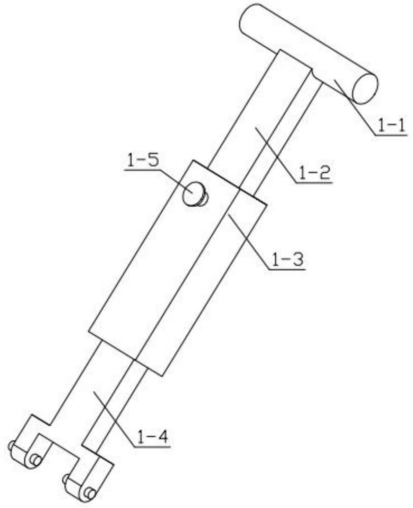
[0037] Combine below Figure 1-16Describe this embodiment, this embodiment will further explain the first embodiment, the telescopic handle 1 includes an armrest 1-1, a telescopic rod 1-2, a telescopic tube 1-3, a hinge 1-4, and a positioning screw 1-5 , the armrest 1-1 is fixedly installed on one end of the telescopic rod 1-2, and the other end of the telescopic rod 1-2 is slidably installed in the groove provided on the telescopic tube 1-3, and the positioning screw 1-5 passes through the telescopic tube 1- 3 is threadedly connected with the handrail 1-1, and the telescopic tube 1-3 is fixedly equipped with a hinge 1-4, and the hinge 1-4 is hinged with the U-shaped frame 3.

specific Embodiment approach 3

[0038] Combine below Figure 1-16 Describe this embodiment, and this embodiment will further explain Embodiment 1. The limit mechanism 2 includes a fixed head 2-1, a two-way threaded rod 2-2, a fixed head 2-3, and a top sprocket 2- 4. Limit slider 2-5, limit plate 2-6, one end of the two-way threaded rod 2-2 is installed in the groove provided on the fixed head 2-1, and the two-way threaded rod 2-2 The other end is rotatably installed in the groove provided on the fixed head two 2-3, the top sprocket 2-4 is fixedly installed on the two-way threaded rod one 2-2, and the limit slide 2-5 is connected with the two-way threaded rod one 2-2. 2 threaded connection, the limit plate 2-6 is rotatably installed on the limit slider 2-5, the fixed head 2-1 and the fixed head 2 2-3 are fixedly installed on the U-shaped frame 3, the limit slide 2 -5 is slidably mounted on the U-shaped frame 3.


PUM


Abstract

The present invention relates to decoration-related devices, more specifically a floor tile gap cleaning device, including a telescopic handle, a limit mechanism, a U-shaped frame, a synchronous adjustment mechanism, a collection box and a cleaning mechanism. The limit mechanism is fixed and installed On the U-shaped frame, the U-shaped frame is hinged with the telescopic handle, the synchronous adjustment mechanism is engaged with the limit mechanism, the synchronous adjustment mechanism is rotatably installed on the U-shaped frame, the cleaning mechanism is fixedly installed on the U-shaped frame, and the collection box rotates Installed on the cleaning mechanism, the synchronous adjustment mechanism is threadedly connected with the collection box; this device can clean the sand and stones in the gaps of the floor tiles by rotating and cleaning, avoiding sand and stones stuck in the gaps, and the cleaning effect is good. The device has the ability to adjust the distance function, it can adapt to floor tiles of different sizes, and the device has a position calibration function, which can move stably along the gap without manual calibration operation.

Description

technical field [0001] The invention relates to decoration-related devices, more specifically a device for cleaning gaps in floor tiles. Background technique [0002] The beauty seam refers to the filling of the tile gap with the beauty seam agent. The decorative effect of beautiful seams is relatively strong. It can not only enhance the overall sense of luxury of the tiles, but also help to clean the tiles, because there are gaps when laying tiles, and debris will fall into the gaps. Don't worry about this problem. During the construction of beautiful joints, workers use vacuum cleaners to clean the gaps between tiles. This method is slow in cleaning speed, loud in the cleaning process, and poor in cleaning effect. It also requires manual alignment of the suction tube of the vacuum cleaner. Gap and move, troublesome operation. Contents of the invention [0003] The technical problem mainly solved by the present invention is to provide a floor tile gap cleaning device. T...

Claims


Application Information

Patent Timeline
Patent Type & Authority Patents(China)
IPC IPC(8): A47L11/24A47L11/40
CPCA47L11/24A47L11/40A47L11/4036A47L11/4069
Inventor 刘春艳
Owner 创际建工集团有限公司
Why Eureka
Try Eureka