Self-cleaning device for mountainous area curve spherical mirror

A spherical mirror and self-cleaning technology, applied in the field of spherical mirrors, can solve the problems of high time cost, ineffective function, high wiring cost, and achieve the effect of increasing evaporation and increasing cleaning effect.

Inactive Publication Date: 2021-04-30
牛永耀
View PDF9 Cites 0 Cited by
  • Summary
  • Abstract
  • Description
  • Claims
  • Application Information

AI Technical Summary

Problems solved by technology

As a result, its functions cannot be effectively brought into play. If it is cleaned regularly by manpower, it will take a lot of time and cost due to the complex terrain of the mountainous area. There are also some existing electric-driven cleaning equipment to clean it, but the wiring cost is also high, and it is also expensive. It consumes electric energy, so a self-cleaning device for mountain curved spherical mirrors is needed to solve this problem

Method used


Image

  • Self-cleaning device for mountainous area curve spherical mirror
  • Self-cleaning device for mountainous area curve spherical mirror
  • Self-cleaning device for mountainous area curve spherical mirror

Examples


Embodiment 1

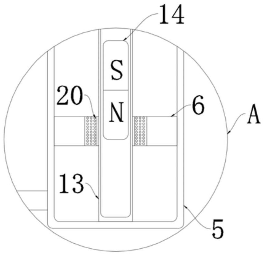
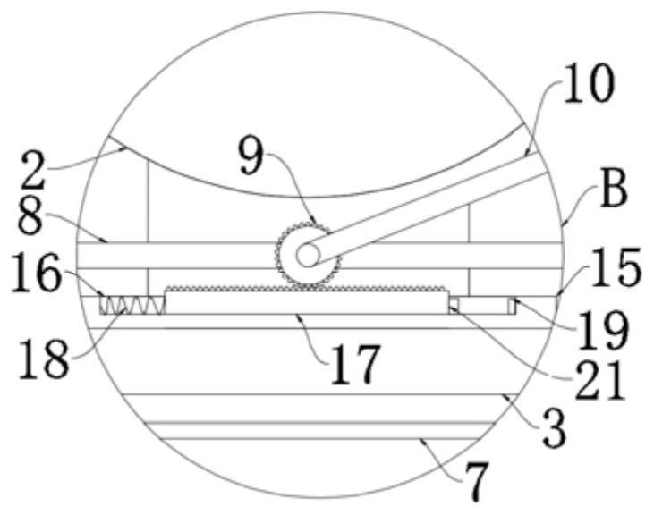
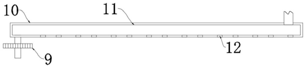
[0037] refer to Figure 1-4 , a self-cleaning device for a curved spherical mirror in mountainous areas, comprising a support column 1 fixed on the ground and a spherical mirror body 2 fixed on the support column 1, and an installation box 3 is fixedly connected to the side wall of the support column 1;

[0038] The wall of the installation box 3 is provided with a liquid storage cavity, and the bottom of the liquid storage cavity is fixedly connected with a heat conduction plate 25 that runs through the installation box 3. The low boiling point evaporating liquid 4 is housed in the liquid storage cavity. 4. Realize that when the sun shines on the heat conduction plate 25, the temperature of the heat conduction plate 25 rises, so that the low boiling point evaporating liquid 4 reaches the evaporation temperature, thereby providing steam as the power of the whole device;

[0039] Two installation cylinders 5 are fixedly connected in the installation box 3, and slide plugs 6 are...

Embodiment 2

[0053] refer to Figure 5-6 The difference between this embodiment and Embodiment 1 is that liquid storage tanks 22 are arranged on both sides of the liquid storage chamber, and concentrated nitric acid is filled in the two liquid storage tanks 22;

[0054] The side walls of the two liquid storage tanks 22 are provided with heat conduction rods 23 connected to the heat conduction plates 25;

[0055] Two concave mirrors 24 are arranged on the installation box 3 , and the focal points of the two concave mirrors 24 are all concentrated on the heat conducting plate 25 .

[0056] The filling volume of the concentrated nitric acid is three-quarters of the liquid storage tank 22, and the two liquid storage tanks 22 are made of transparent glass. By setting the concentrated nitric acid, when the heat is insufficient, the concentrated nitric acid reacts to release heat, so that the low Boiling point evaporating liquid 4.

[0057] The working principle of this embodiment is that in wi...


PUM


Abstract

The invention discloses a self-cleaning device for a mountainous area curve spherical mirror. The self-cleaning device comprises a support column fixed on the ground and a spherical mirror body fixed on the support column, and the side wall of the support column is fixedly connected with a mounting box; a liquid storage cavity is formed in the wall of the mounting box, a heat conduction plate penetrating through the mounting box is fixedly connected to the bottom in the liquid storage cavity, and low-boiling-point evaporation liquid is contained in the liquid storage cavity; two mounting cylinders are fixedly connected into the mounting box, sliding plugs are slidably connected into the two mounting cylinders, and the lower ends of the two mounting cylinders are in sealed communication with the liquid storage cavity through pipelines; and a water tank is fixedly connected in the mounting box, the bottom of the water tank communicates with the upper end of the left-end mounting cylinder through a water inlet pipe, and a one-way valve only allowing water to enter the left-end mounting cylinder from the water tank is arranged at the communicating position. According to the self-cleaning device, the spherical mirror can be automatically cleaned, so that manpower and material resources are greatly saved, the spherical mirror keeps good light reflection, and the possibility of meeting collision is reduced.

Description

technical field [0001] The invention relates to the technical field of spherical mirrors, in particular to a self-cleaning device for curved spherical mirrors in mountainous areas. Background technique [0002] The spherical mirror can display the road conditions on the other side of the curve, which can facilitate the driver to know the situation on the other side of the curve in time, and can largely avoid traffic accidents when passing cars. [0003] Due to the complex road conditions in mountainous areas, the spherical mirror will accumulate some dust on its surface if it is placed beside the road for a long time. As a result, its functions cannot be effectively brought into play. If it is cleaned regularly by manpower, it will take a lot of time and cost due to the complex terrain of the mountainous area. There are also some existing electric-driven cleaning equipment to clean it, but the wiring cost is also high, and it is also expensive. Consumed electric energy, so ...

Claims


Application Information

Patent Timeline
Patent Type & Authority Applications(China)
IPC IPC(8): B08B11/00B08B1/04B08B3/02
CPCB08B11/00B08B1/005B08B1/04B08B3/02
Inventor 牛永耀
Owner 牛永耀
Why Eureka
Try Eureka