Anti-fog deicing automobile windshield

A technology for windshields and automobiles, applied to windshields, vehicle maintenance, vehicle parts, etc., can solve problems such as the inability to use resistance wires, long action time, and melting of frost, so as to improve the heat preservation effect, defogging and deicing speed Fast, the effect of improving the speed of melting ice

Inactive Publication Date: 2021-04-30
烟台慧博特产业研究院有限公司
View PDF0 Cites 0 Cited by
  • Summary
  • Abstract
  • Description
  • Claims
  • Application Information

AI Technical Summary

Problems solved by technology

[0002] In areas with higher latitudes, the winter temperature is lower, and frost is easy to form inside the front windshield of the car. The existing technology uses an internal air conditioner, and the maximum air volume is blown to the glass to melt the indoor frost with a large amount of hot air. In the case of thick frost, The effect time is long, because the wind cannot blow to the outside of the glass, the frost on the outside of the glass can only rely on the temperature rise to slowly melt, and the front windshield cannot be heated by resistance wire, because the resistance wire will block the line of sight, so the front windshield How to quickly defog and deice the glass is the problem to be solved by this device

Method used


Image

  • Anti-fog deicing automobile windshield
  • Anti-fog deicing automobile windshield
  • Anti-fog deicing automobile windshield

Examples


Embodiment 1

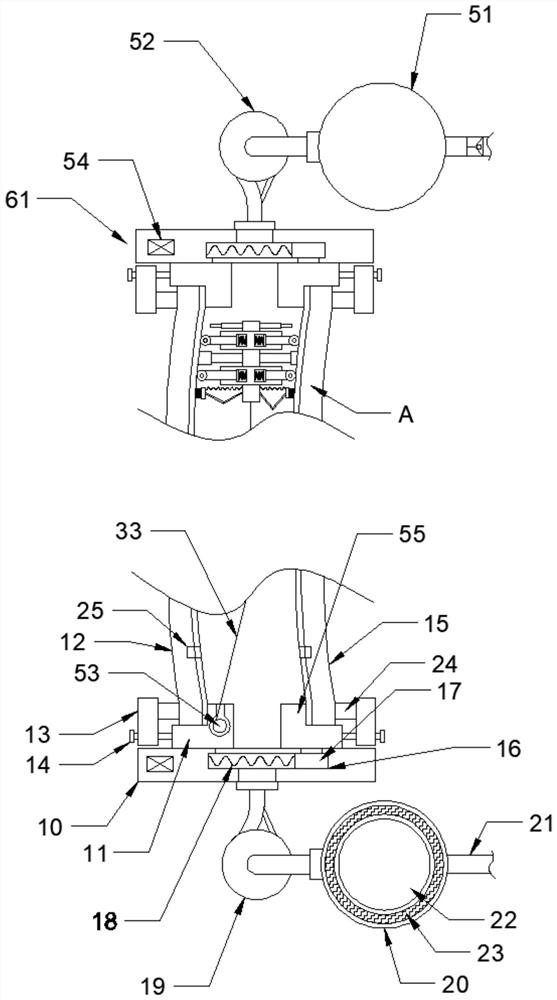
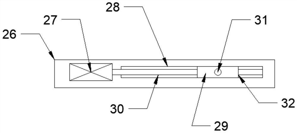
[0031]Preferably, Embodiment 1: the gap control device 61 includes a control body 26, the control body 26 is provided with a control chute 28, and the control chute 28 is slidably provided with a control slider 29, and the control slider 29 The middle is provided with threaded hole 32, and described control chute 28 wall bodies are rotated to be provided with threaded rod 30, and described threaded hole 32 is threadedly connected with described threaded rod 30, and described control chute 28 wall body is provided with control motor 27, so The shaft of the control motor 27 is fixedly connected to the threaded rod 30 , the front side of the control slider 29 is fixedly provided with a connecting rod 31 , and the connecting rod 31 is fixedly connected to the rear seat 55 .

Embodiment 2

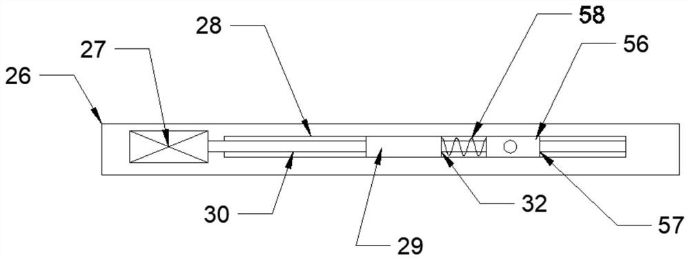
[0032] Embodiment 2: the gap control device 61 includes a control body 26, the control body 26 is provided with a control chute 28, and the control chute 28 is slidably provided with a control slider 29, and the middle of the control slider 29 is provided with Threaded hole 32, the wall of the control chute 28 is rotated and provided with a threaded rod 30, the threaded hole 32 is threadedly connected to the threaded rod 30, the wall of the control chute 28 is provided with a control motor 27, and the control motor The shaft of 27 is fixedly connected with the threaded rod 30, the control chute 28 is slidably provided with a control block 56, the middle of the control block 56 is provided with a through hole 57, and the through hole 57 passes through the threaded rod 30, so A pressure spring 58 is provided between the control block 56 and the control slider 29 , and a connecting rod 31 is fixedly arranged on the front side of the control block 56 , and the connecting rod 31 is ...


PUM


Abstract

The invention relates to the technical field of windshields, and discloses an anti-fog deicing automobile windshield which comprises heat insulation seats symmetrically arranged up and down, front glass is arranged between the upper heat insulation seat and the lower heat insulation seat, rear glass is arranged on the inner side of the front glass, a certain gap is formed between the front glass and the rear glass, a center rod is arranged in the gap between the front glass and the rear glass, and an elastic body is arranged in the middle of the center rod. When the device is used, a traditional front windshield can be replaced, the device has the liquid heating function, a good driving view can be provided for a driver; in addition, the mode that liquid makes direct contact with the front windshield for heating is adopted by the device, the heat conduction efficiency is high; and compared with traditional air conditioner gas heating, the device has the advantages that the ice dissolving speed is obviously increased, the demisting and deicing speed is high, and energy consumption is small.

Description

technical field [0001] The invention relates to the technical field of windshields, in particular to an anti-fog and deicing automobile windshield. Background technique [0002] In areas with higher latitudes, the winter temperature is lower, and frost is easy to form inside the front windshield of the car. The existing technology uses an internal air conditioner, and the maximum air volume is blown to the glass to melt the indoor frost with a large amount of hot air. In the case of thick frost, The effect time is long, because the wind cannot blow to the outside of the glass, the frost on the outside of the glass can only rely on the temperature rise to slowly melt, and the front windshield cannot be heated by resistance wire, because the resistance wire will block the line of sight, so the front windshield How to demist and deice the glass quickly is the problem to be solved by this device. Contents of the invention [0003] The object of the present invention is to pro...

Claims


Application Information

Patent Timeline
Patent Type & Authority Applications(China)
IPC IPC(8): B60J1/00B60S1/02
CPCB60J1/001B60J1/002B60S1/026
Inventor 张玉娥
Owner 烟台慧博特产业研究院有限公司
Why Eureka
Try Eureka