Fabricated steel-concrete composite structure culvert

A combined structure and concrete technology, applied in the field of structural culverts, can solve problems such as extended construction period, scattered construction points, and slow installation process

Inactive Publication Date: 2021-04-30
闫志伟
View PDF0 Cites 2 Cited by
  • Summary
  • Abstract
  • Description
  • Claims
  • Application Information

AI Technical Summary

Problems solved by technology

[0002] The traditional culvert engineering construction method is mostly on-site vertical formwork pouring, which has many disadvantages, such as scattered construction points, difficult control of construction quality, long cycle of turnover of formwork and support materials, construction progress is greatly affected by winter and rainy seasons, and construction period is long. The problem is usually solved by the method of prefabricated steel concrete composite structure
[0003] In the existing prefabricated steel-concrete composite structure culverts, the bottom plate is generally installed first, then the side plates are installed, and finally the top plat

Method used


Image

  • Fabricated steel-concrete composite structure culvert
  • Fabricated steel-concrete composite structure culvert
  • Fabricated steel-concrete composite structure culvert

Examples


Embodiment 1

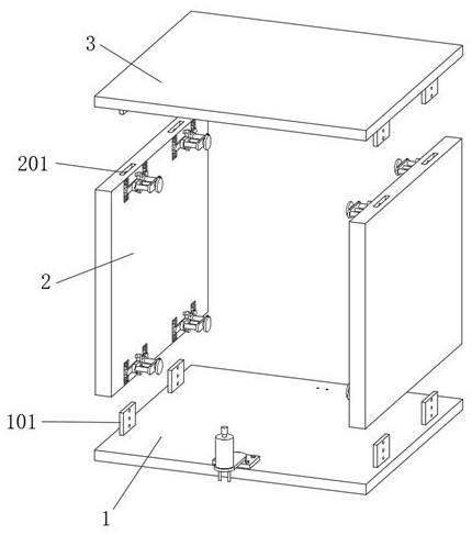
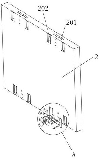
[0033] Such as Figure 1-7 The culvert of a prefabricated steel-concrete composite structure includes a base plate main body 1, a standing plate main body 2 and a top plate main body 3. The upper surface of the base plate main body 1 is fixedly connected with four sets of first inserts 101, four sets of first inserts 101 It is symmetrically distributed in pairs. The side wall of the first plug 101 is provided with a first locking hole 1011. The bottom of the top plate main body 3 is fixedly connected with a second plug 301. The position of the second plug 301 is the same as that of the first plug 101. Correspondingly, the side wall of the second plug 301 is provided with a second locking hole 3011, and the top and bottom of the stand main body 2 are provided with positioning grooves 201 corresponding to the first plug 101 and the second plug 301. A plug 101 and a second plug 301 are movably inserted in the positioning groove 201, the side wall of the main body 2 of the stand i...

Embodiment 2

[0037] Embodiment 2 is a further improvement to Embodiment 1.

[0038] Such as Figure 1-7An assembled steel-concrete composite structure culvert is shown, including a base plate main body 1, a standing plate main body 2 and a top plate main body 3. The upper surface of the base plate main body 1 is fixedly connected with four sets of first inserts 101, four sets of first inserts 101 are symmetrically distributed in pairs. The side wall of the first insert 101 is provided with a first locking hole 1011. The bottom of the top plate main body 3 is fixedly connected with a second insert 301. The position of the second insert 301 is the same as that of the first insert. Corresponding to 101, the side wall of the second plug 301 is provided with a second locking hole 3011, and the top and bottom of the stand main body 2 are provided with positioning grooves 201 corresponding to the first plug 101 and the second plug 301, The first plug 101 and the second plug 301 are movably inser...

Embodiment 3

[0043] Embodiment 3 is a further improvement to Embodiment 1.

[0044] Such as Figure 1-7 An assembled steel-concrete composite structure culvert is shown, including a base plate main body 1, a standing plate main body 2 and a top plate main body 3. The upper surface of the base plate main body 1 is fixedly connected with four sets of first inserts 101, four sets of first inserts 101 are symmetrically distributed in pairs. The side wall of the first insert 101 is provided with a first locking hole 1011. The bottom of the top plate main body 3 is fixedly connected with a second insert 301. The position of the second insert 301 is the same as that of the first insert. Corresponding to 101, the side wall of the second plug 301 is provided with a second locking hole 3011, and the top and bottom of the stand main body 2 are provided with positioning grooves 201 corresponding to the first plug 101 and the second plug 301, The first plug 101 and the second plug 301 are movably inse...


PUM


Abstract

The invention relates to the technical field of structural culverts, in particular to a fabricated steel-concrete composite structure culvert which comprises a bottom plate body, a standing plate body and a top plate body, first inserting blocks are fixedly connected to the upper surface of the bottom plate body, the four sets of first inserting blocks are symmetrically distributed in pairs, and first locking holes are formed in the side walls of the first inserting blocks. A second inserting block is fixedly connected to the bottom of the top plate body, a second locking hole is formed in the side wall of the second inserting block, positioning grooves are formed in the top and the bottom of the standing plate body, fixing mechanisms corresponding to the first inserting block and the second inserting block are arranged on the side wall of the standing plate body, and a positioning hole is formed in one side of the upper surface of the bottom plate body; a locking mechanism is arranged on the other side of the upper surface of the bottom plate main body, when the bottom plate main body, the standing plate main body and the top plate main body are mounted, positioning and mounting of the bottom plate main body, the standing plate main body and the top plate main body are facilitated, the splicing time is saved, the accuracy of the mounting position is guaranteed, and the bottom plate main body, the standing plate main body and the top plate main body can be temporarily fixed.

Description

technical field [0001] The invention relates to the technical field of structural culverts, in particular to an assembled steel-concrete composite structure culvert. Background technique [0002] The traditional culvert engineering construction method is mostly on-site vertical formwork pouring, which has many disadvantages, such as scattered construction points, difficult control of construction quality, long cycle of turnover of formwork and support materials, construction progress is greatly affected by winter and rainy seasons, and construction period is long. The problem is usually solved by the method of prefabricated steel concrete composite structure. [0003] In the existing prefabricated steel-concrete composite structure culverts, the bottom plate is generally installed first, then the side plates are installed, and finally the top plate is installed on the top of the two side plates. The bottom plate, side plates and top plate are fixed by concrete. The culvert ...

Claims


Application Information

Patent Timeline
IPC IPC(8): E01F5/00
CPCE01F5/005
Inventor 闫志伟
Owner 闫志伟
Why Eureka
Try Eureka