
Current transformer auxiliary wiring device

A technology of current transformer and auxiliary wiring, applied in the field of electric power, can solve the problems of low efficiency of verification work and great potential safety hazard.

Pending Publication Date: 2021-04-30
国网新疆电力有限公司营销服务中心 +1
View PDF0 Cites 0 Cited by
  • Summary
  • Abstract
  • Description
  • Claims
  • Application Information

AI Technical Summary

Problems solved by technology

[0004] The invention provides an auxiliary wiring device for a current transformer, which overcomes the deficiencies of the above-mentioned prior art, and can effectively solve the problem that the two secondary terminals arbitrarily designated by the current transformer cannot be quickly short-circuited in the existing transformer wiring terminals. As a result, the verification work efficiency is low and the safety hazard is large.

Method used


Image

  • Current transformer auxiliary wiring device
  • Current transformer auxiliary wiring device
  • Current transformer auxiliary wiring device

Examples


Embodiment Construction

[0018] The present invention is not limited by the following examples, and specific implementation methods can be determined according to the technical solutions of the present invention and actual conditions.

[0019] In the present invention, for the convenience of description, the description of the relative positional relationship of each component is based on the description attached to the description. figure 1 For example, the positional relationship of front, rear, top, bottom, left, right, etc. is determined according to the layout direction of the drawings in the description.

[0020] Below in conjunction with embodiment and accompanying drawing, the present invention will be further described:

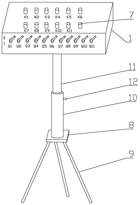
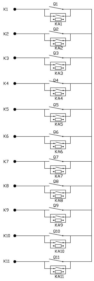
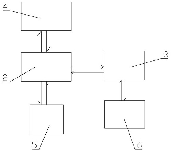
[0021] as attached figure 1 , 2 , 3, the current transformer auxiliary wiring device includes a housing 1, the surface of the housing 1 is provided with terminals K1 to Kn, the surface of the housing 1 is provided with manual switches Q1 to Qn, and one end of the manual sw...


PUM


Abstract

The invention relates to the technical field of electric power, in particular to a current transformer auxiliary wiring device which comprises a shell, wiring terminals K1 to Kn are arranged on the surface of the shell, manual switches Q1 to Qn are arranged on the surface of the shell, one ends of the manual switches Q1 to Qn are connected to the wiring terminals K1 to Kn in series in a one-to-one correspondence mode, and the other ends of the manual switches Q2 to Qn are connected with the manual switches Q1. A triangular support used for adjusting the height of the shell is arranged at the bottom of the shell. The device is reasonable and compact in structure and convenient to use, the purpose of short-circuiting any two secondary side terminals of the current transformer can be achieved by controlling the closing states of the manual switches Q1 to Qn, and therefore when the secondary current of the current transformer is verified to be different transformation ratios of 1A, independent wire changing short-circuit operation does not need to be carried out on different terminals; and the workload of workers is reduced, the calibration work efficiency is improved, the risk of mistaken electric shock of the workers is avoided, and the characteristics of high efficiency, rapidness and safety are achieved.

Description

technical field [0001] The invention relates to the field of electric power technology, and relates to an auxiliary wiring device for a current transformer. Background technique [0002] At present, the current transformer automatic wiring device used in the laboratory can solve the following problems: 1. The 0.05 (S) to 0.01 (S) standard current transformer has many transformation ratios, and the corresponding primary winding and secondary winding have many taps. It is necessary to change the primary line and the secondary line, and the automatic wiring device of the current transformer can complete the wiring at one time, avoiding frequent line changes with different transformation ratios, reducing the labor intensity of the staff, and shortening the verification time; The primary line and secondary line of the transformer must correspond to the corresponding transformation ratio wiring, so that wiring errors and poor contact of the wires often occur, which improves the te...

Claims


Application Information

Patent Timeline
IPC IPC(8): G01R35/02G01R1/04G01R35/00
CPCG01R35/02G01R1/0416G01R35/007
Inventor 苏亚洲陈涛李宁杨金成杨永建李广山尹文庆谢珍潘成龙
Owner 国网新疆电力有限公司营销服务中心
Learn More