Endoscope optical system

An optical system and endoscope technology, applied in the field of endoscopy, can solve the problems of the endoscope becoming too large, unable to match the CMOS image sensor, and not suitable for large-size image sensors, etc.

Active Publication Date: 2021-04-30
SHANGHAI AOHUA PHOTOELECTRICITY ENDOSCOPE
View PDF12 Cites 0 Cited by
  • Summary
  • Abstract
  • Description
  • Claims
  • Application Information

AI Technical Summary

Problems solved by technology

[0005] The endoscopic objective lens described in the above-mentioned patent document 1 and patent document 2 adopts a longer objective lens structure to ensure that the light height of the peripheral field of view light on all mirror groups is small, so that the entire objective lens can be enlarged during the zooming process. Each lens group has small off-axis aberrations and can be corrected by the moving lens group, but this structure is not suitable for large-scale image sensors with high pixels, which will lead to the giantization of the entire endoscope; in addition, although the patent Document 3 can achieve a compact design, but like Patent Document 1 and Patent Document 2, the incident angle of the chief ray on the image plane at the edge of the field of view is small and changes with the magnification of the objective lens, so it cannot match the lens with a large CRA CMOS image sensor required

Method used


Image

  • Endoscope optical system
  • Endoscope optical system
  • Endoscope optical system

Examples


Embodiment 1

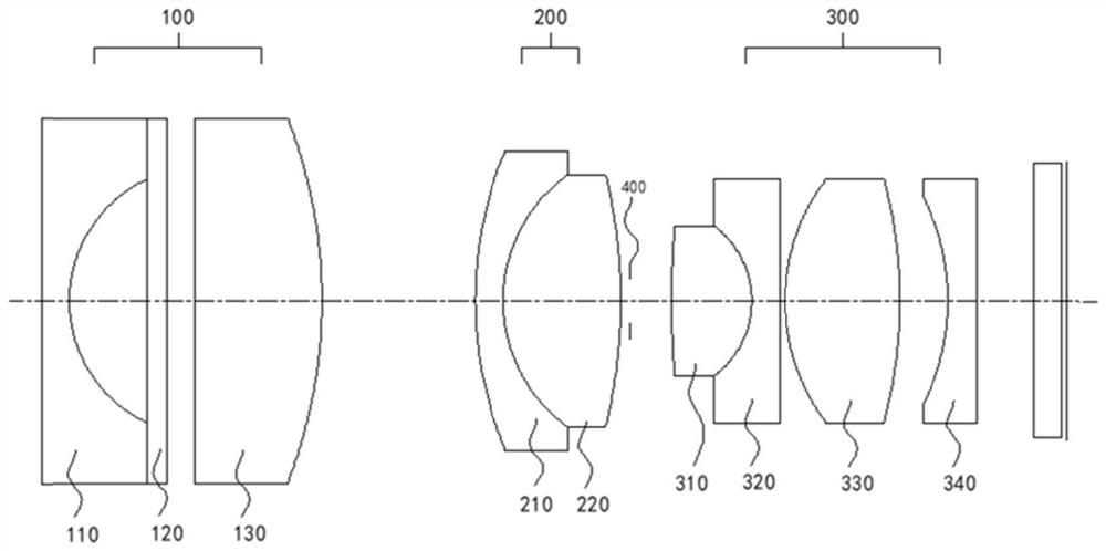
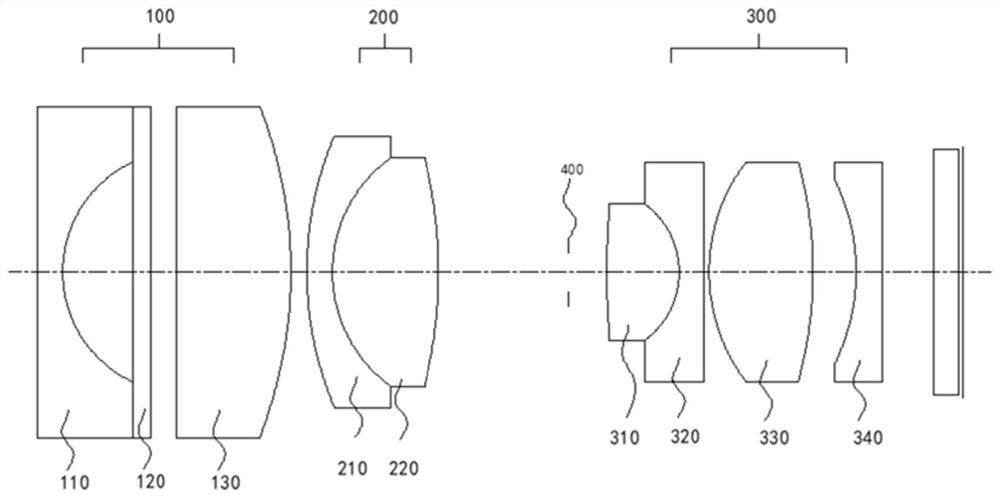
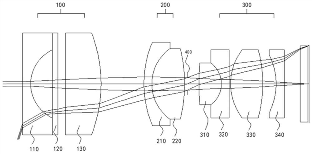
[0093] see Figure 3-Figure 8 , represents the state when the second lens group 200 moves to the image plane side, that is, the farthest point observation state, and the state where the second lens group 200 moves to the object side, that is, the closest point observation state, based on the above-mentioned second lens group 200 status.

[0094] For details, refer to the data in Table 1, Table 2, and Table 3, which are the parameters and test results of specific experimental tests in this example.

[0095] Table 1

[0096]

[0097]

[0098] Table 2

[0099] routine observation status Zoom in to observe the state at close range do 10.000 2.10 D6 1.636 0.194 D9 0.100 1.542 Field of view 145.000 95 Fno 8.000 8

[0100] table 3

[0101] Conditional value W1 72.5 W2 47.5 |f1 / f3| 0.50 θ 31.99 |f2 / f1| 0.73 |f2 / f3| 0.37 TT / ymax 7.36 d / ft 0.98

Embodiment 2

[0103] see Figure 9-Figure 14 , represents the state when the second lens group 200 moves to the image plane side, that is, the farthest point observation state, and the state when the second lens group 200 moves to the object side, that is, the closest point observation state. Based on the above-mentioned second lens group 200 status.

[0104] Specifically refer to the data in Table 4, Table 5, and Table 6, which are the parameters and test results of specific experimental tests in this example.

[0105] Table 4

[0106]

[0107] table 5

[0108]

[0109]

[0110] Table 6

[0111] Conditional value W1 72.5 W2 47.5 |f1 / f3| 0.59 θ 33.00 |f2 / f1| 0.70 |f2 / f3| 0.41 TT / ymax 6.83 d / ft 1.06

Embodiment 3

[0113] see Figure 15-Figure 20 , represents the state when the second lens group 200 moves to the image plane side, that is, the farthest point observation state, and the state when the second lens group 200 moves to the object side, that is, the closest point observation state. Based on the above-mentioned second lens group 200 status.

[0114] For details, refer to the data in Table 7, Table 8, and Table 9, which are the parameters and test results of specific experimental tests in this example.

[0115] Table 7

[0116]

[0117]

[0118] Table 8

[0119] routine observation status Zoom in to observe the state at close range do 15.0000 2.20 D6 2.354 0.484 D9 0.100 1.970 Field of view 170.000 95 Fno 8.000 8

[0120] Table 9

[0121] Conditional value W1 85.0 W2 47.5 |f1 / f3| 0.28 θ 30.00 |f2 / f1| 0.67 |f2 / f3| 0.19 TT / ymax 7.75 d / ft 1.25

[0122] From the da...


PUM


Abstract

The invention discloses an endoscope optical system which comprises a first lens group, a second lens group and a third lens group which are sequentially arranged from an object side, and zooming of the optical system is carried out by moving the second lens group on an optical axis, wherein the third lens group comprises at least one positive cemented lens, a negative cemented lens, a positive lens and a negative lens which are arranged in sequence; the second lens group is composed of a positive cemented lens and a negative cemented lens; the first lens group is composed of a plano-concave lens and a convex lens; the concave surface of the plano-concave lens is arranged towards the image surface; the convex lens is arranged towards the object surface. According to the scheme, the compact endoscope optical system with aberration well corrected can be matched with a high-pixel CMOS image sensor with a large CRA requirement, has an optical amplification function and has an ultra-clear observation effect.

Description

technical field [0001] The invention relates to the technical field of endoscopes, in particular to an endoscope optical system with a zoom function. Background technique [0002] In modern medical examinations, endoscopes can be used to inspect lesions in the human body, and in order to directly complete the diagnosis of lesions in the human body, endoscopes with magnified observation functions can be used. The endoscope with magnified observation function contains a zoom objective lens, which has the characteristics of a large field of view in the normal observation state and is suitable for overall observation; while in the short-distance state, the optical zoom is realized by switching the position of the internal lens, which has the characteristics of The characteristics of the small field of view are suitable for local observation. For example, the following patents have realized the zoom-in observation function of the endoscope objective lens. [0003] Japanese Paten...

Claims


Application Information

Patent Timeline
Patent Type & Authority Applications(China)
IPC IPC(8): G02B15/14A61B1/00
CPCG02B15/143A61B1/0019
Inventor 李强
Owner SHANGHAI AOHUA PHOTOELECTRICITY ENDOSCOPE
Why Eureka
Try Eureka