Endoscope optical system

An optical system and endoscope technology, applied in the field of endoscopy, can solve the problems of inability to match high-pixel large-size CMOS image sensors, inability to match image sensors, etc.

Active Publication Date: 2021-05-04
SHANGHAI AOHUA PHOTOELECTRICITY ENDOSCOPE
View PDF5 Cites 1 Cited by
  • Summary
  • Abstract
  • Description
  • Claims
  • Application Information

AI Technical Summary

Problems solved by technology

Obviously, the compact design on the premise of proportionally reducing the size of the system cannot match the high-pixel and large-size CMOS image sensor
[0012] In addition, the objective optical systems described in Patent Document 1, Patent Document 2, and Patent Document 3 have a peripheral field of view light incident on the image plane that is close to the telecentric design, which obviously cannot match the image sensor required by the large CRA

Method used


Image

  • Endoscope optical system
  • Endoscope optical system
  • Endoscope optical system

Examples


Embodiment 1

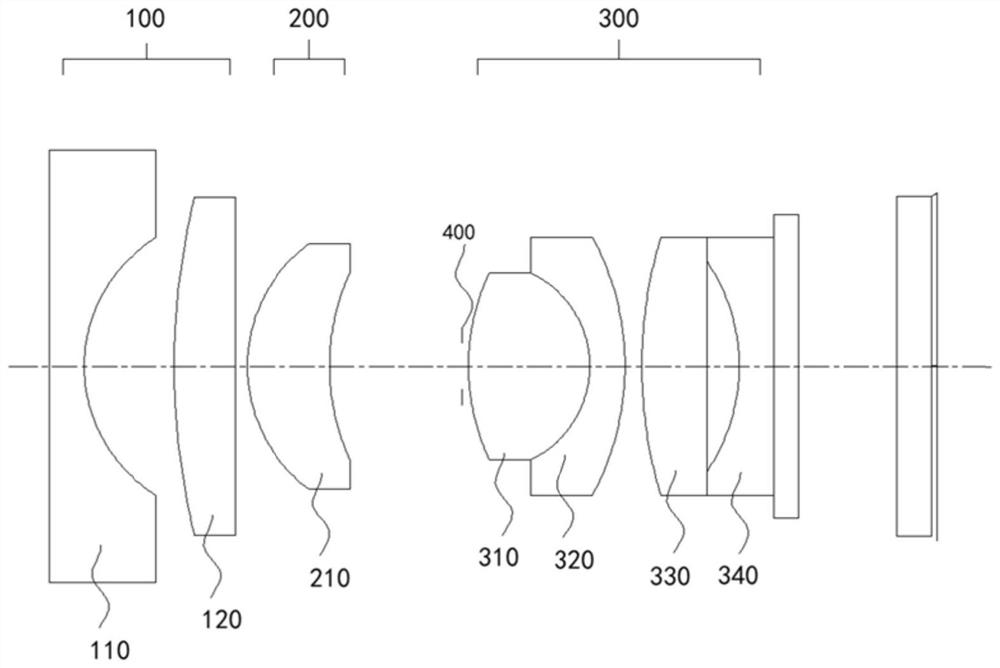
[0079] see Figure 3-Figure 6 , represents the state when the second lens group 200 moves to the object side, that is, the farthest point observation state, and the state when the second lens group 200 moves to the image plane side, that is, the closest point observation state, based on the above-mentioned second lens group 200 status,

[0080] For details, refer to the data in Table 1, Table 2, and Table 3, which are the parameters and test results of specific experimental tests in this example.

[0081] Table 1

[0082] Numbering radius thickness Refractive index Abbe number SO Infinity 15.000 1 Infinity 0.300 1.883 40.87 2 1.291 0.772 3 6.106 0.525 1.850 30.06 4 Infinity 0.100 5 1.310 0.705 1.487 70.42 6 1.948 1.139 stop Infinity 0.050 8 1.870 1.040 1.618 63.41 9 -0.882 0.300 1.620 36.35 10 -2.339 0.145 11 3.896 0.558 1.618 63.41 12 Infi...

Embodiment 2

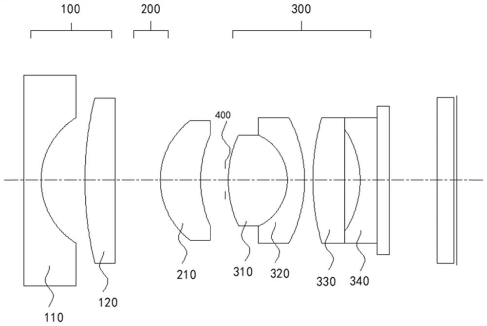
[0089] see Figure 7-Figure 10 , represents the state when the second lens group 200 moves to the object side, that is, the farthest point observation state, and the state when the second lens group 200 moves to the image plane side, that is, the closest point observation state, based on the above-mentioned second lens group 200 status.

[0090] Specifically refer to the data in Table 4, Table 5, and Table 6, which are the parameters and test results of specific experimental tests in this example.

[0091] Table 4

[0092]

[0093]

[0094] table 5

[0095] Farthest point observation state Closest observation status do 15.000 3.900 D4 0.100 0.866 D6 1.332 0.566 Half field angle (°) 72.0 71.6 Fno 7.5 7.6

[0096] Table 6

[0097] Conditional value θ 35.8 |f1 / f3| 1.30 |f1 / ft| 1.67 TT / IH 5.07 d / ft 0.50

Embodiment 3

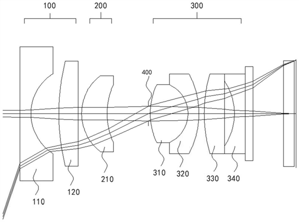
[0099] see Figure 11-Figure 14 , represents the state when the second lens group 200 moves to the object side, that is, the farthest point observation state, and the state when the second lens group 200 moves to the image plane side, that is, the closest point observation state, based on the above-mentioned second lens group 200 status.

[0100] Specifically refer to the data in Table 7, Table 8, and Table 9, which are the parameters and test results of specific experimental tests in this example.

[0101] Table 7

[0102] Numbering radius thickness Refractive index Abbe number SO Infinity 18.000 1 Infinity 0.300 1.883 40.87 2 1.556 0.877 3 5.459 0.610 1.904 31.32 4 Infinity 0.100 5 1.519 0.654 1.487 70.42 6 2.243 1.240 stop Infinity 0.231 8 1.961 0.856 1.618 63.41 9 -1.121 0.300 1.673 32.18 10 -2.738 0.215 11 2.909 0.616 1.618 63.41 12 In...


PUM


Abstract

The invention discloses an endoscope optical system which includes a first lens group, a second lens group, and a third lens group arranged in order from an object side. A farthest point object is focused to a nearest point object by moving the second lens group on an optical axis. The third lens group comprises at least one positive bonding lens, a negative bonding lens, a positive lens and a negative lens which are arranged in sequence; the second lens group is a focusing lens, and the convex surface faces an image surface; and the first lens group is composed of a plano-concave lens whose concave surface faces the image surface and a convex lens whose convex surface faces the image surface. The scheme is the compact endoscope optical system with well corrected aberration, and the system can be matched with a high-pixel CMOS image sensor with a large CRA requirement, and has an optical focusing function and an ultra-clear observation effect.

Description

technical field [0001] The invention relates to the technical field of endoscopes, in particular to an endoscope optical system. Background technique [0002] In modern medical examinations, endoscopes can be used to inspect lesions in the human body, and for finer inspection of lesions, lesion images with higher image quality are required. This requires the selection of an image sensor with higher pixels, and requires the endoscope optical system to have a better observation depth of field. Compared with the previous endoscopic optical system, matching high-pixel image sensors requires a larger focal length, and at the same aperture, the corresponding depth of field will become smaller. However, if the depth of field is expanded by reducing the aperture, the image quality will be poor due to diffraction, and the overall brightness of the image will decrease, so an endoscope optical system with a focusing function is required. And in order to have a wider observation field...

Claims


Application Information

Patent Timeline
IPC IPC(8): G02B15/14A61B1/00
CPCG02B15/143A61B1/00096A61B1/00163
Inventor 李强
Owner SHANGHAI AOHUA PHOTOELECTRICITY ENDOSCOPE
Why Eureka
Try Eureka