LED surface mounting method

A surface mount, LED chip technology, applied in the direction of electrical components, circuits, semiconductor devices, etc., can solve the problem of low mounting efficiency and achieve the effect of improving efficiency

Pending Publication Date: 2021-04-30
深圳市山本光电股份有限公司
View PDF7 Cites 3 Cited by
  • Summary
  • Abstract
  • Description
  • Claims
  • Application Information

AI Technical Summary

Problems solved by technology

When mounting and mounting, it is necessary to mount and paste a large number of LED chips on the flexible circuit board. The mounting efficiency of the current LED surface mount method is low.

Method used

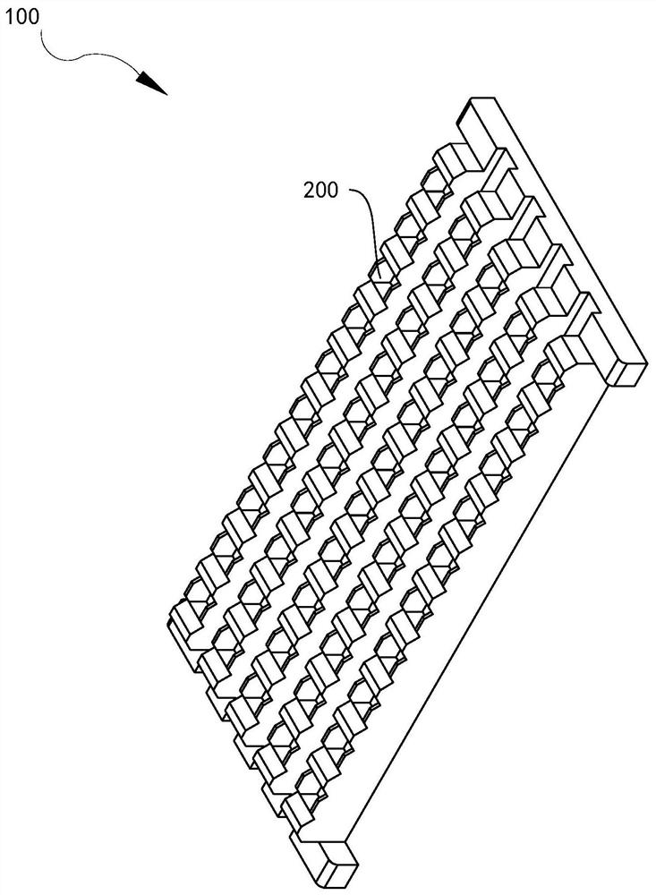
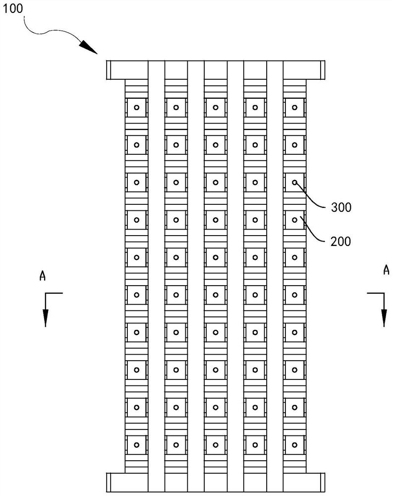
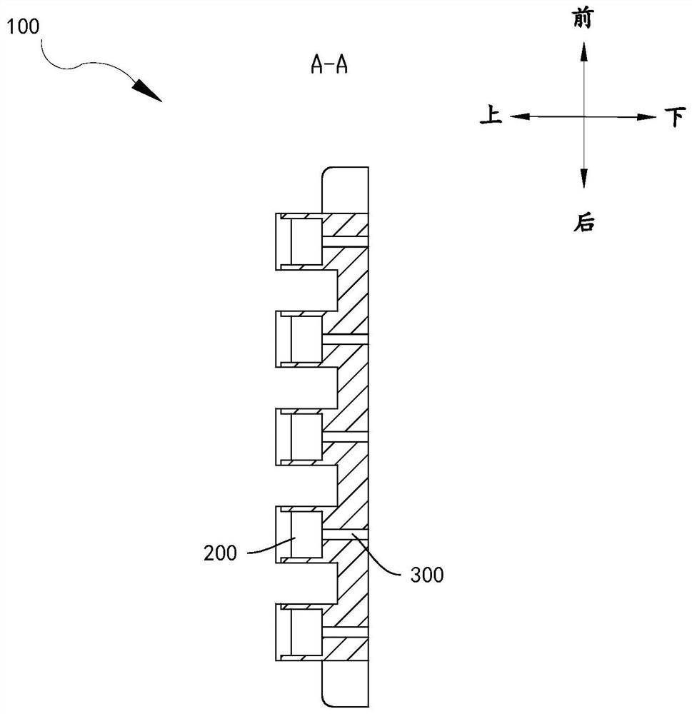

Image

  • LED surface mounting method
  • LED surface mounting method
  • LED surface mounting method

Examples


Embodiment Construction

[0029] The conception and technical effects of the present invention will be clearly and completely described below in conjunction with the embodiments, so as to fully understand the purpose, features and effects of the present invention. Apparently, the described embodiments are only some of the embodiments of the present invention, rather than all of them. Based on the embodiments of the present invention, other embodiments obtained by those skilled in the art without creative efforts belong to The protection scope of the present invention.

[0030] In the description of the embodiments of the present invention, if it involves orientation descriptions, for example, the orientation or positional relationship indicated by "up", "down", "left", "right" etc. is based on the orientation or positional relationship shown in the drawings, It is only for the convenience of describing the present invention and simplifying the description, but does not indicate or imply that the device...


PUM


Abstract

The invention discloses an LED surface mounting method. The LED surface mounting method comprises the following steps that a flexible circuit board is assembled on a flexible circuit board fixing clamp, solder paste is printed on a bonding pad of the flexible circuit board, LED chips are transferred to an LED jig, fixing grooves of the LED jig are distributed in an array mode, the LED chips are transferred to the bonding pad of the flexible circuit board from the LED jig, and reflow soldering is conducted on the flexible circuit board. By adopting the following steps of assembling the flexible circuit board, printing the solder paste, expanding the wafer, transferring and reflowing the LED chips and the like and the LED jig with the fixing grooves distributed in the array, a plurality of LED chips can be mounted at one time when the LED chips are mounted, so that the LED surface mounting efficiency is improved.

Description

technical field [0001] The invention relates to the technical field of LED production, in particular to an LED surface mounting method. Background technique [0002] LED surface mount is an indispensable part in the production of LED products, and its mounting efficiency has a great influence on the efficiency of the entire LED production. When mounting and mounting, a large number of LED chips need to be mounted and mounted on the flexible circuit board, and the mounting efficiency of the current LED surface mounting method is low. Contents of the invention [0003] The present invention aims to solve at least one of the technical problems existing in the prior art. For this reason, the present invention proposes an LED surface mounting method, which improves the efficiency of LED surface mounting. [0004] According to the LED surface mount method of the embodiment of the first aspect of the present invention, the LED surface mount method includes the following steps: ...

Claims


Application Information

Patent Timeline
Patent Type & Authority Applications(China)
IPC IPC(8): H01L33/48H01L33/00H01L33/62
CPCH01L33/486H01L33/005H01L33/62
Inventor 黄欣李建华
Owner 深圳市山本光电股份有限公司
Why Eureka
Try Eureka