
Low-noise fan motor

A fan motor, low-noise technology, used in electromechanical devices, cooling/ventilation devices, electrical components, etc., can solve problems such as motor heat dissipation problems

Active Publication Date: 2021-04-30
CINDERSON TECH (SUZHOU) CO LTD
View PDF5 Cites 0 Cited by
  • Summary
  • Abstract
  • Description
  • Claims
  • Application Information

AI Technical Summary

Problems solved by technology

[0004] The purpose of the present invention is to provide a low-noise fan motor to solve the above-mentioned background technology. The existing fan motors are mostly based on passive heat dissipation to dissipate heat from the motor body. Therefore, motor users urgently need a new type of low-noise and high-efficiency heat dissipation. Advanced mechanical structure to solve the problem of motor heat dissipation

Method used

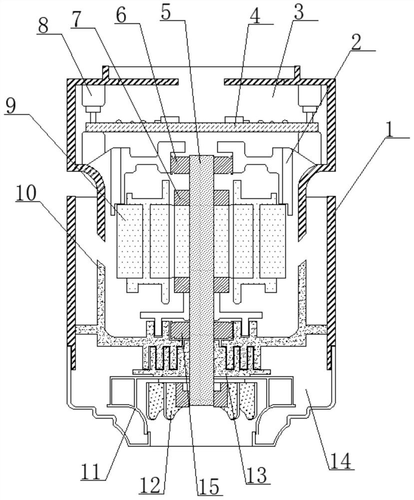
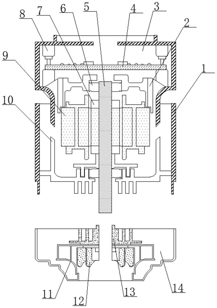
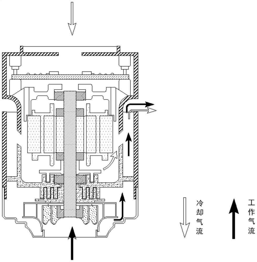

Image

  • Low-noise fan motor
  • Low-noise fan motor
  • Low-noise fan motor

Examples


Embodiment Construction

[0022] The following will clearly and completely describe the technical solutions in the embodiments of the present invention with reference to the accompanying drawings in the embodiments of the present invention. Obviously, the described embodiments are only some, not all, embodiments of the present invention. Based on the embodiments of the present invention, all other embodiments obtained by persons of ordinary skill in the art without making creative efforts belong to the protection scope of the present invention.

[0023] In the description of the present invention, it should be noted that the terms "upper", "lower", "inner", "outer", "front end", "rear end", "both ends", "one end", "another end" The orientation or positional relationship indicated by etc. is based on the orientation or positional relationship shown in the drawings, and is only for the convenience of describing the present invention and simplifying the description, rather than indicating or implying that ...


PUM


Abstract

The invention discloses a low-noise fan motor, which comprises a motor shell and an air guide sleeve, the air guide sleeve is arranged on the top side of the motor shell, the air guide sleeve is formed at a top end opening of the motor shell in an overhead mode from the motor shell, and a bearing positioning frame is arranged at the position, close to the bottom edge, of the inner side of the air guide sleeve, the bearing positioning frame is integrally formed in the air guide sleeve, a PCB main board is arranged on the top side of the bearing positioning frame, main board positioning rods are arranged at the corners of the PCB main board in the vertical direction, the main board positioning rods are positioned at the corners of the PCB main board in a penetrating mode, and an upper fixing bearing is arranged on the inner side of the bearing positioning frame and located at the circle center, and the upper fixing bearing is embedded into the inner side of the bearing positioning frame from the port of the bearing positioning frame.

Description

technical field [0001] The invention belongs to the technical field related to motors, and in particular relates to a low-noise fan motor. Background technique [0002] The motor is a device that converts electrical energy into mechanical energy. It uses a energized coil to generate a rotating magnetic field and acts on the rotor to form a magnetoelectric force. The motor is divided into DC motors and AC motors according to the power supply used. The motors in the power system are large Part of it is an AC motor, which can be a synchronous motor or an asynchronous motor. The motor is mainly composed of a stator and a rotor. The direction of the current-carrying wire in the magnetic field is related to the direction of the current and the direction of the magnetic induction line. [0003] The existing fan motor technology has the following problems: the existing fan motor is mostly based on passive heat dissipation to dissipate heat from the main body of the motor, so motor u...

Claims


Application Information

Patent Timeline
Patent Type & Authority Applications(China)
IPC IPC(8): H02K9/06H02K9/10
CPCH02K9/06H02K9/10
Inventor 朱云舫
Owner CINDERSON TECH (SUZHOU) CO LTD
Learn More