A linear motor with a shaft

A motor and axis technology, used in instruments, propulsion systems, electric components, etc., can solve problems such as poor roundness, weakened vibration, friction noise, etc., and achieve the effect of preventing resonance frequency changes, preventing defects, and avoiding deformation.

Active Publication Date: 2022-03-22
阜南县特立电子有限公司
View PDF0 Cites 0 Cited by
  • Summary
  • Abstract
  • Description
  • Claims
  • Application Information

AI Technical Summary

Problems solved by technology

[0003] When the existing linear motor presses the upper surface of the upper case, frictional noise may occur due to the change in resonance frequency due to the deformation of the upper case and the contact between parts, and when the roundness of the coil is not good, Existing products will generate friction noise due to contact with coils and other parts during motor operation, when external pressure is applied to the upper surface of the upper case, the resonance frequency changes due to the deformation of the spring engaged with the upper case, and the amount of vibration due to Weaken with frequency change

Method used


Image

  • A linear motor with a shaft
  • A linear motor with a shaft
  • A linear motor with a shaft

Examples


Embodiment 1

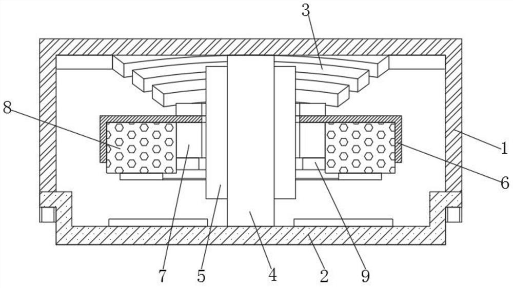
[0056] Such as Figure 1-2 As shown, a linear motor with a shaft includes an upper casing 1 and a lower casing 2, a spring 3 is fixedly installed on the inner top wall of the upper casing 1, and the lower casing 2 is located directly below the upper casing 1 , a bobbin 4 is arranged between the upper casing 1 and the lower casing 2, and the bobbin 4 is fixed on the lower casing 2 to provide support for the upper casing 1, thereby providing support for the upper casing 1 and avoiding the upper casing The shell 1 is deformed, so as to prevent the change of the resonance frequency caused by the deformation of the upper shell 1 and the friction noise due to the contact between the components, and fundamentally prevent the defects caused by the deformation of the upper shell 1, said The outer surface of the bobbin 4 is wound with an electromagnetic coil 5, and an outer locking block 6 is arranged between the upper casing 1 and the lower casing 2, and the outer locking block 6 is a ...

Embodiment 2

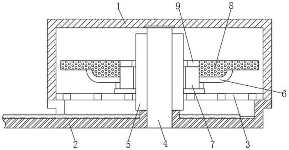
[0092] Such as image 3 As shown, the difference between this embodiment and Embodiment 1 is that the spring 3 is arranged on the inner top wall of the lower casing 2 in the form of a leaf spring, and the outer locking block 6, the ring magnet 7, the vibrator 8 and the inner locking block 9 is arranged above the spring 3, and the installation method of the outer lock block 6, the ring magnet 7, the vibrator 8 and the inner lock block 9 is a mirror image of that in Embodiment 1;

[0093] Since the spring 3 is a leaf spring, it does not require heat treatment and does not protrude, so it is easy to handle during the manufacturing process, thereby reducing the defective rate, all parts are assembled in the lower case 2, and the upper case 1 is assembled after final inspection, Therefore, the assembly is simple and the defective rate is reduced.

[0094] A linear motor with a shaft, when working, by setting the bobbin 4 between the upper casing 1 and the lower casing 2, the upper...


PUM


Abstract

The invention belongs to the field of mechanical equipment and relates to linear motor technology, in particular to a linear motor with a shaft. A linear motor with a shaft, comprising an upper casing and a lower casing, a spring is fixedly installed on the inner top wall of the upper casing, the lower casing is located directly below the upper casing, the upper casing and the lower casing A spool is arranged between the shells, an electromagnetic coil is wound on the outer surface of the spool, and an outer locking block is arranged between the upper casing and the lower casing, and the outer locking block is a cover with a lower opening, and the outer There is a through hole in the center of the lock block, and the inner top wall of the outer lock block is fixed with a ring magnet and a vibrator. The ring magnet is located between the vibrator and the bobbin, and the bottom of the ring magnet is provided with an inner lock block. . The invention provides support for the upper casing by fixing the bobbin on the lower casing, thereby providing support for the upper casing, avoiding the deformation of the upper casing, and preventing the change of resonance frequency caused by the deformation of the upper casing.

Description

technical field [0001] The invention belongs to the field of mechanical equipment and relates to linear motor technology, in particular to a linear motor with a shaft. Background technique [0002] Linear motors generally refer to linear motors. Linear motors are a kind of transmission device that directly converts electrical energy into linear motion mechanical energy without any intermediate conversion mechanism. It can be regarded as a rotating motor that is cut radially and developed into Planar; linear motors are also called linear motors, linear motors, linear motors, and push rod motors. The most commonly used types of linear motors are plate type, U-shaped groove type, and tubular type. The typical composition of the coil is three-phase, which is composed of Hall The components realize brushless commutation. [0003] When the existing linear motor presses the upper surface of the upper case, frictional noise may occur due to the change in resonance frequency due to ...

Claims


Application Information

Patent Timeline
Patent Type & Authority Patents(China)
IPC IPC(8): H02K41/02H02K5/24G01R31/34G01H17/00
CPCH02K41/02H02K5/24G01R31/343G01H17/00
Inventor 金春会李伟德
Owner 阜南县特立电子有限公司
Why Eureka
Try Eureka