Supercharge Your Innovation With Domain-Expert AI Agents!

Flaw detection device based on visual sensor and detection method thereof

A visual sensor and defect detection technology, which is applied to grinding drive devices, machine tools suitable for grinding workpiece edges, and parts of grinding machine tools, etc., can solve problems such as deformation of cylindrical pipes, failure of detection results, etc. , to ensure the accuracy and reduce the effect of detection errors

Active Publication Date: 2021-05-04
江苏维讯工业技术有限公司
View PDF12 Cites 0 Cited by
  • Summary
  • Abstract
  • Description
  • Claims
  • Application Information

AI Technical Summary

Problems solved by technology

[0003] However, there are still some problems in the existing detection device. When the existing detection device detects the inner wall of the columnar pipeline, it is necessary to penetrate the visual detection device on the detection device into the inside of the columnar pipeline, and then rotate the visual detection device. It can complete the inspection of the inner wall of the columnar pipe, but when the thickness of the columnar pipe is thin or the texture is soft, the columnar pipe placed on the loading platform will be deformed at this time, and then when the detection device detects the deformed columnar pipe, Furthermore, in the process of converting the captured target into an image signal, the visual sensor will extract the wrong features of the target from the deformed columnar pipeline, which will lead to the failure of the detection result

Method used


Image

  • Flaw detection device based on visual sensor and detection method thereof
  • Flaw detection device based on visual sensor and detection method thereof
  • Flaw detection device based on visual sensor and detection method thereof

Examples


Embodiment Construction

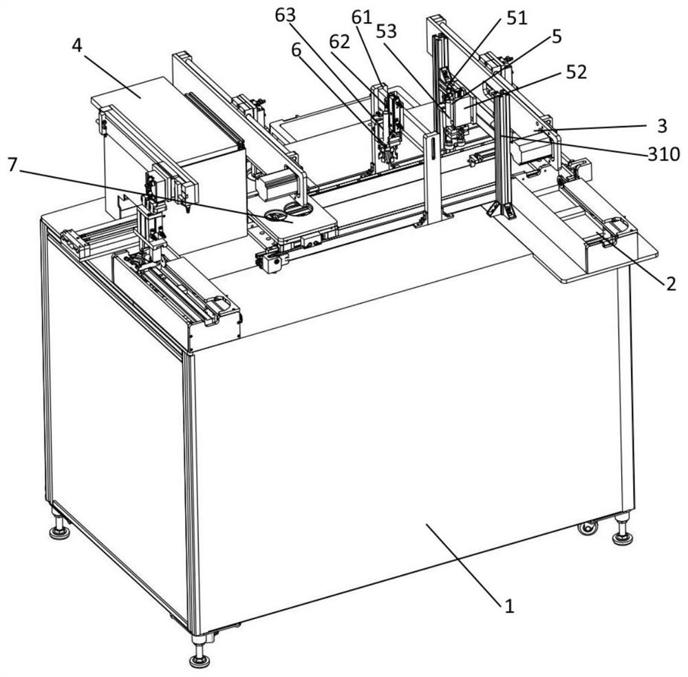
[0034] After the applicant's research and analysis, the reason for this problem (the visual sensor will extract the wrong features of the target from the deformed columnar pipeline, which will lead to the failure of the detection result) is that the existing detection device is performing the inspection on the inner wall of the columnar pipeline. During the detection work, it is necessary to penetrate the visual detection device on the detection device into the interior of the columnar pipe, and then rotate the visual detection device to complete the inspection of the inner wall of the columnar pipe. However, when the thickness of the cylindrical pipe is thin or the texture is soft, At this time, the columnar pipe placed on the loading platform will be deformed, and when the detection device detects the deformed columnar pipe, the visual sensor will detect the deformed Extracting the wrong features of the target will lead to the failure of the detection results; in order to com...


PUM


Abstract

The invention discloses a flaw detection device based on a visual sensor and a detection method thereof. The flaw detection device based on the visual sensor comprises a workbench, a feeding device, a discharging device, a set of conveying mechanisms arranged on the workbench, at least three carrying mechanisms, a marking device, a polishing mechanism and a detecting mechanism, wherein the feeding device and the discharging device are installed on the workbench, the carrying mechanisms are installed on the workbench, the marking device is arranged on the workbench, and the polishing mechanism and the detecting mechanism are installed on the workbench. According to the flaw detection device, through an arranged supporting device, a columnar pipeline can be supported, deformation of the columnar pipeline is avoided, and then the detection error of the detection device can be reduced; meanwhile, a connecting frame can rotate around a transmission lead screw, the visual sensor can be driven to start rotating, and then detection work of the inner wall of the columnar pipeline can be completed; meanwhile, the supporting device is located above the visual sensor, it is guaranteed that the deformation quantity of an area detected by the visual sensor is small, and the accuracy of a detection result is guaranteed.

Description

technical field [0001] The invention relates to a detection device, in particular to a defect detection device based on a visual sensor, and relates to the detection field of the visual sensor. Background technique [0002] Defect detection is to use machines instead of human eyes for measurement and judgment. Defect detection refers to devices or components such as smart cameras, visual controllers, or visual sensors that convert the ingested target into image signals, and then through the image processing system, various operations are performed on these signals to extract the characteristics of the target, and then according to The results of the discrimination are used to complete the detection of the detected object. [0003] However, there are still some problems in the existing detection device. When the existing detection device detects the inner wall of the columnar pipeline, it is necessary to penetrate the visual detection device on the detection device into the ...

Claims


Application Information

Patent Timeline
Patent Type & Authority Applications(China)
IPC IPC(8): B24B9/00B24B29/04B24B41/02B24B41/06B24B47/04B24B47/22B24B49/12
CPCB24B29/04B24B9/007B24B41/02B24B47/04B24B41/067B24B47/22B24B49/12
Inventor 张武蒋伟宋燕燕
Owner 江苏维讯工业技术有限公司
Features
  • R&D
  • Intellectual Property
  • Life Sciences
  • Materials
  • Tech Scout
  • Unparalleled Data Quality
  • Higher Quality Content
  • 60% Fewer Hallucinations
Learn More