Rounding method for cable sheath

A sheath and cable technology, which is applied to the complete circle of the cable sheath, can solve the problems of no cylinder box suction and return, inability to save water resources, inability to accelerate the cooling and cooling of the sheath and other problems, so as to save water resources. , to ensure the effect of rounding requirements

Pending Publication Date: 2021-05-04
TONGDING INTERCONNECTION INFORMATION CO LTD
View PDF7 Cites 2 Cited by
  • Summary
  • Abstract
  • Description
  • Claims
  • Application Information

AI Technical Summary

Problems solved by technology

[0003] But in the prior art, the rounding device of the cable sheath only simply makes the sheath cable pass through the shaping sleeve, resulting in: 1. There is no vacuum setting in the cylindrical box, and the surface of the sheath cannot be tightly attached The round shaped sleeve cannot guarantee the roundness of the sheath surface; 2. There is no spray setting in the cylindrical box, which cannot accelerate the cooling and shaping of the sheath, and cannot guarantee the rounding requirements of the sheath during movement; 3. There is no cylindrical box The setting of suction and return cannot resist the vacuum suction to ensure the return of water for reuse, and cannot save water resources

Method used


Image

  • Rounding method for cable sheath
  • Rounding method for cable sheath
  • Rounding method for cable sheath

Examples


Embodiment 1

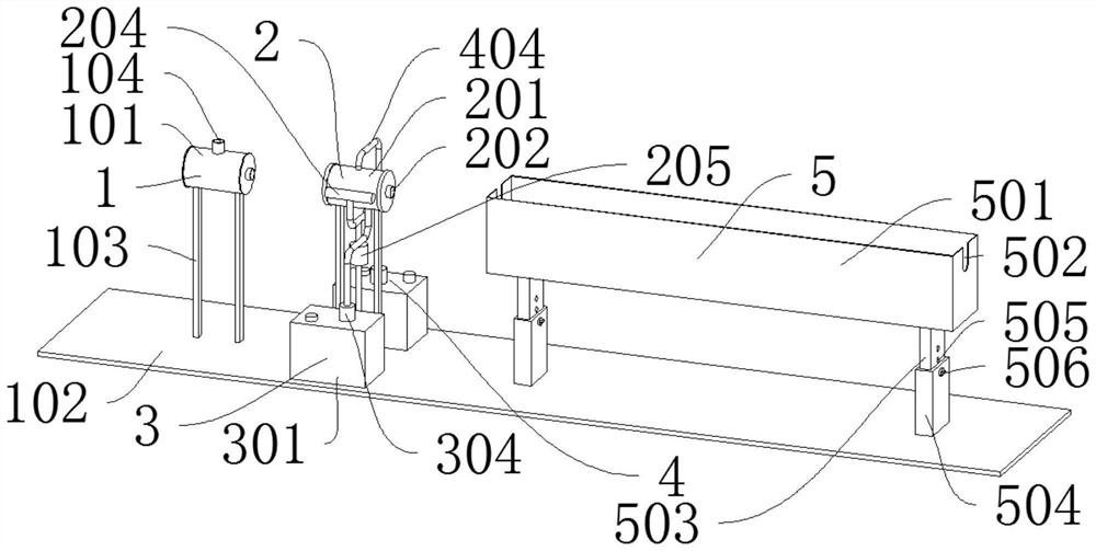
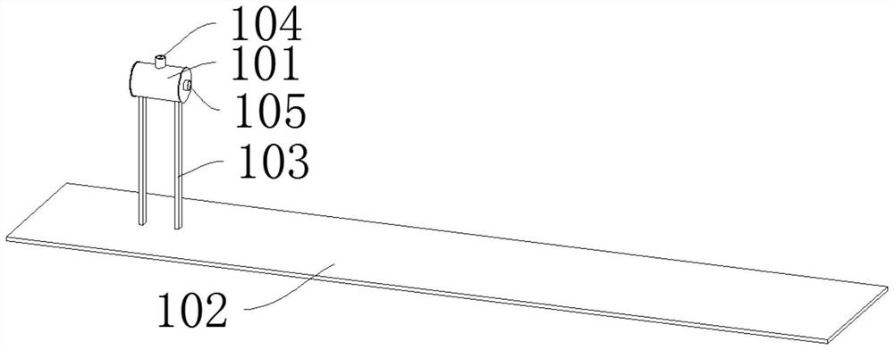
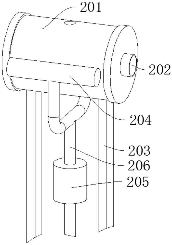
[0032] like Figure 1-Figure 7 As shown, a rounding device for cable sheath includes a host device 1 for cable sheath injection molding, and also includes a rounding shaping device 2 for cable sheathing. The shaping device 2 is installed below There is a water tank device 3 for holding cooling water, an auxiliary tank device 4 for generating vacuum is arranged behind the water tank device 3, and a cooling device 5 for cooling the cable sheath is arranged on one side of the shaping device 2; the host device 1 includes a main body 101, a first outrigger 103 is arranged under the main body 101, a bottom plate 102 is arranged under the first outrigger 103, an injection pipe 104 is arranged on the top of the main body 101, and two inlets and outlets 105 are symmetrically installed at both ends of the main body 101; The device 2 includes a cylindrical box 201. A sizing sleeve 202 is installed in the middle of the cylindrical box 201. The sizing sleeve 202 is a circular straight pipe...

Embodiment 2

[0035] Such as Figure 8 As shown, the difference between Embodiment 2 and Embodiment 1 is that the cooling device 5 includes a water tank box 501, two U-shaped grooves 502 are symmetrically arranged at both ends of the water tank box 501, and two third legs are symmetrically arranged at the bottom of the water tank box 501 503, a number of limit grooves 507 are evenly distributed in front of the third leg 503, a support seat 504 is arranged below the third leg 503, and a locking nail 508 is installed in front of the support seat 504, and the third leg 503 goes up and down along the support seat 504 Slide to adjust the height of the water tank box 501, and the locking nail 508 is locked and inserted into the limit groove 507 in front of the third leg 503 to fix the height of the water tank box 501; It is threadedly connected with the support base 504 , the sliding connection ensures the flexible movement of the third leg 503 , and the threaded connection ensures the locking of...


PUM


Abstract

The invention discloses a rounding method for a cable sheath. The method comprises the steps that a cable passes through a cylindrical box at a certain speed, the surface of the sheath is tightly attached to a circular shaping sleeve through the vacuum setting in the cylindrical box, and the roundness of the surface of the sheath is ensured; through the spraying arrangement in the cylindrical box, cooling and shaping of the sheath are accelerated, and the rounding requirement of the sheath in the moving process is met; and through the arrangement of suction backflow of the cylindrical box, vacuum suction force is resisted, water liquid backflow recycling is guaranteed, and water resources are saved.

Description

technical field [0001] The invention relates to the technical field of cable production, in particular to a method for rounding a cable sheath. Background technique [0002] The cable jacket is the outermost layer of the cable. The sheathed cable is extruded (winded) around the conductor with an insulating layer, such as an overhead insulated cable, or several cores twisted (corresponding to the phase wire, neutral wire and ground wire of the power system), such as an overhead insulated cable with more than two cores, or Add a sheath layer, such as plastic / rubber sheathed wires and cables. It is mainly used for the transmission of strong electric energy in the transmission, distribution, transmission, transformation, and power supply lines. The passing current is large (tens of amps to thousands of amps), and the voltage is high (220V to 500kV and above). The roundness and diameter of the cable sheath affect the appearance of the sheathed cable and the uniformity of wind r...

Claims


Application Information

Patent Timeline
IPC IPC(8): B29C48/90B29C48/885B29C48/88B29C48/06B29L31/34
CPCB29C48/905B29C48/885B29C48/919B29C48/06B29L2031/3462
Inventor 戴杰沈林林戴伟斌庄武勇
Owner TONGDING INTERCONNECTION INFORMATION CO LTD
Why Eureka
Try Eureka