
Blow molding mold not using compressed gas for blow molding

A technology of blow molding and compressed gas, which is applied in the field of blow molding that can replace compressed gas for blow molding, and can solve problems such as precise requirements for exhaust apertures

Inactive Publication Date: 2021-05-04
曹均梅
View PDF6 Cites 1 Cited by
  • Summary
  • Abstract
  • Description
  • Claims
  • Application Information

AI Technical Summary

Problems solved by technology

[0003] The present invention proposes a blow mold that can replace compressed gas for blow molding. Aperture Precision Requirements

Method used


Image

  • Blow molding mold not using compressed gas for blow molding
  • Blow molding mold not using compressed gas for blow molding
  • Blow molding mold not using compressed gas for blow molding

Examples


Embodiment Construction

[0020] The following will clearly and completely describe the technical solutions in the embodiments of the present invention with reference to the accompanying drawings in the embodiments of the present invention. Obviously, the described embodiments are only some, not all, embodiments of the present invention.

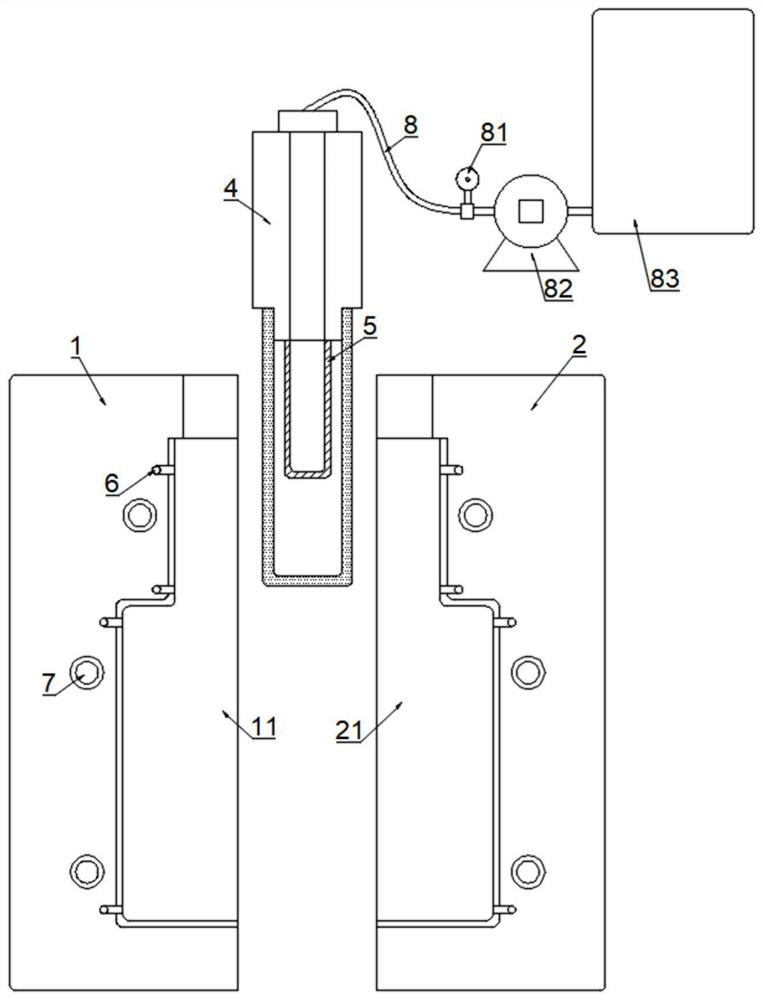
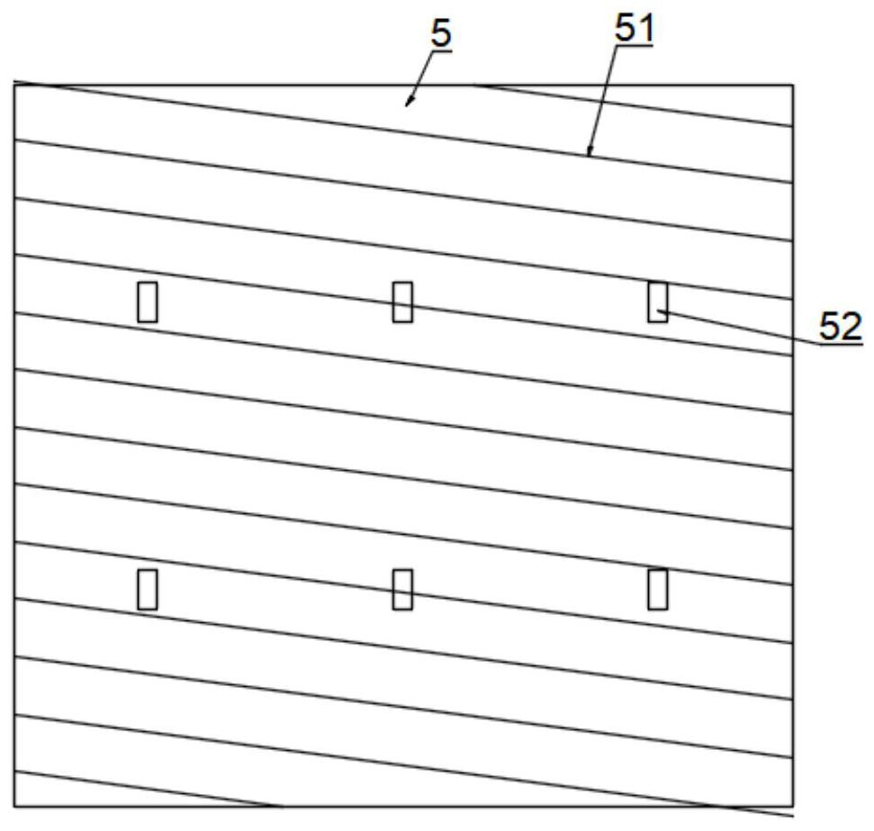
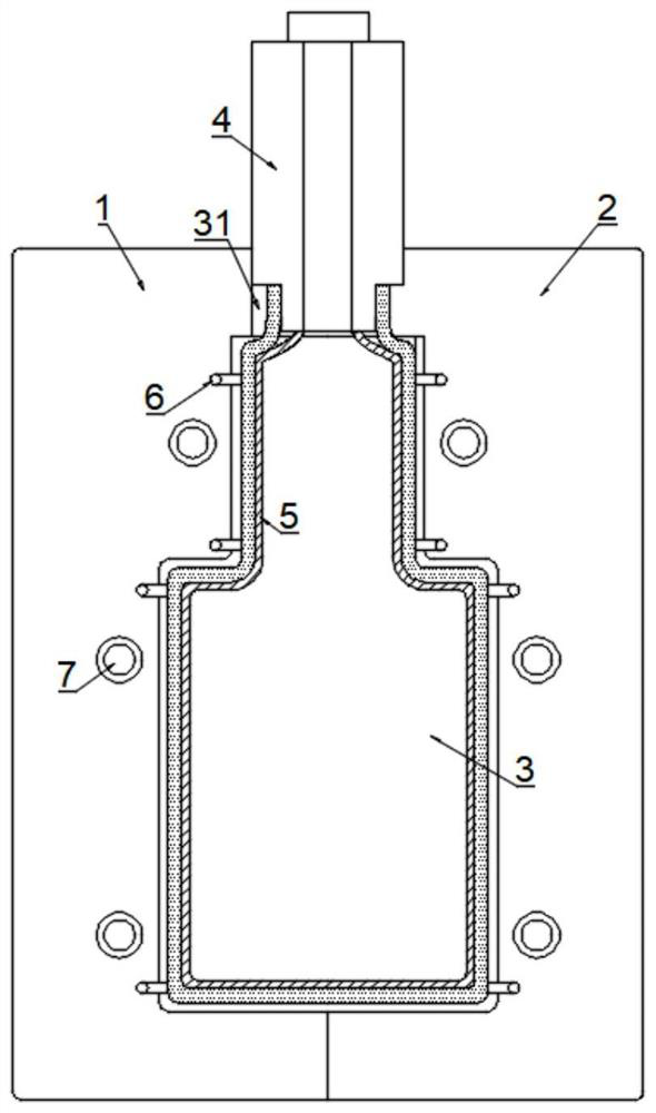
[0021] refer to Figure 1-3 , a blow mold that can replace compressed air for blow molding, including a left mold 1 and a right mold 2, wherein the left mold 1 and the right mold 2 are connected by a guide post to limit sliding and installed on a bracket, and the two halves of the mold pass through the guide The column slides closer to the parting and away from the parting.

[0022] The left mold cavity 11 and the right mold cavity 21 are respectively opened on the adjacent side of the left mold 1 and the right mold 2, wherein the left mold cavity 11 and the right mold cavity 21 form the mold cavity 3 after the left mold 1 and the right mold 2 are closed. The produc...


PUM


Abstract

The invention discloses a blow molding mold not using compressed gas for blow molding, and relates to the technical field of blow molding molds. The blow molding mold not using compressed gas for blow molding comprises a left mold and a right mold, the left mold and the right mold are in limited sliding connection through a guide column and are installed on a support, and the adjacent sides of the left mold and the right mold are provided with a left mold cavity and a right mold cavity respectively, the left mold cavity and the right mold cavity form a mold cavity after the left mold and the right mold are closed, and an air inlet is formed in the top of the mold cavity located on the parting surfaces of the left mold and the right mold. A control circuit of the mold controls electric heating wires to be electrify to generate heat, so that a controllable inner core is heated and deformed into the internal shape of a blow molding part, the deformation force of the inner core is used to form external expansion type extrusion on a parison, and the controllable inner core is completely attached to the parison in the deformation process, so that the stretching states of the periphery of the parison are relatively consistent, and the wall thickness difference caused by the stretching state difference is avoided when non-rotational symmetric products are manufactured by adopting compressed air as a blowing medium.

Description

technical field [0001] The invention relates to the technical field of blow molds, in particular to a blow mold that can replace compressed air for blow molding. Background technique [0002] In the process of making plastic bottles and jars, the blow molding process is generally adopted, that is, the prepared parison is placed in the blow mold, and compressed gas is injected to inflate the parison through the collision of the compressed gas, so that the inflated The parison is tightly attached to the inner wall of the mold, and then cooled and demolded to obtain the corresponding hollow plastic bottle. Existing blow molding molds generally use compressed air as the inflation medium to inflate the parison. During this process, the compressed air needs to be re-pressurized after use; and for non-rotationally symmetrical products, During the inflation process, part of the parison first contacts the mold, and part of it later contacts the mold, resulting in differences in the ...

Claims


Application Information

Patent Timeline
Patent Type & Authority Applications(China)
IPC IPC(8): B29C49/48B29C49/64B29C49/42
CPCB29C49/48B29C49/64B29C49/42
Inventor 王慧萍
Owner 曹均梅
Learn More