

Display panel and display device
A technology for display panels and display areas, applied in semiconductor devices, electrical components, photovoltaic power generation, etc., can solve problems such as wire breakage, achieve good protection, and reduce the risk of wire breakage.
- Summary
- Abstract
- Description
- Claims
- Application Information
AI Technical Summary
Problems solved by technology
Method used
Image

Examples
Embodiment Construction
[0026] The present invention will be further described in detail below in conjunction with the accompanying drawings and embodiments. It should be understood that the specific embodiments described here are only used to explain the present invention, but not to limit the present invention. In addition, it should be noted that, for the convenience of description, only some structures related to the present invention are shown in the drawings but not all structures.
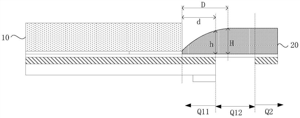
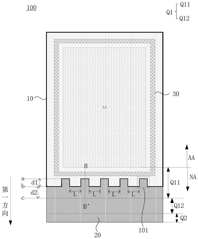
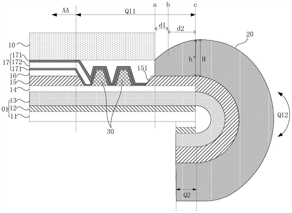
[0027] Exemplary, figure 1 is a structural schematic diagram of an existing display panel, see figure 1 The light-emitting side of the display panel is provided with a polarizer 10. From the edge of the polarizer 10, there is a protective glue 20 above the frame area S1, the bending area S2 and the binding area S3 of the display panel. The protective glue 20 and the polarizer 10 edge contact ( figure 1 not shown), used to protect structures such as wires extending from the display area to the binding area.
[0...
PUM
 Abstract
Description
Claims
Application Information