Nasopharynx suction tube with flushing connector

A technology for flushing the interface and the nasopharynx, which is applied in the field of medical devices and can solve the problems of difficulty in directly guiding the nasopharynx and delaying the progress of the operation.

Pending Publication Date: 2021-05-07
复旦大学附属中山医院厦门医院
View PDF1 Cites 0 Cited by
  • Summary
  • Abstract
  • Description
  • Claims
  • Application Information

AI Technical Summary

Problems solved by technology

[0005] 1. It is difficult to directly introduce it into the nasopharynx, and it must be pulled by other instruments to insert it into the nasopharynx through the mouth;
[0006] 2. When the ...

Method used


Image

  • Nasopharynx suction tube with flushing connector
  • Nasopharynx suction tube with flushing connector
  • Nasopharynx suction tube with flushing connector

Examples


Embodiment 1

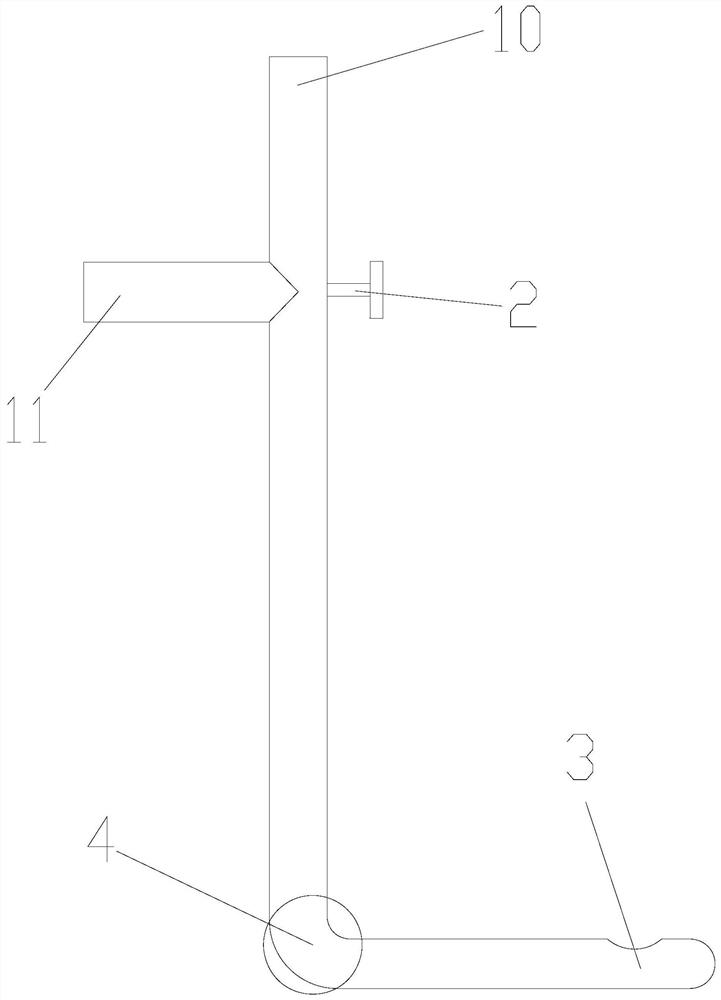
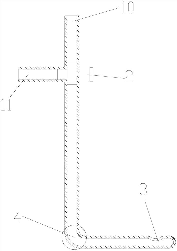
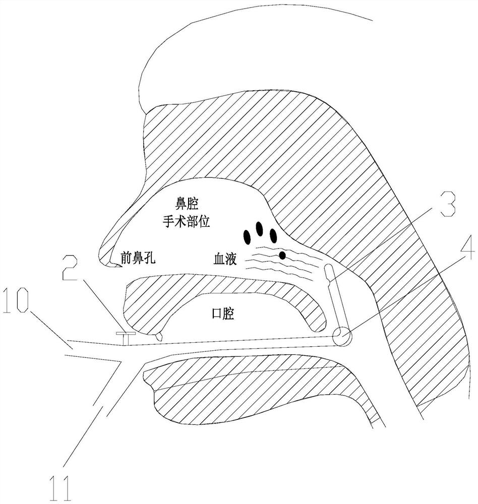
[0031] See Figure 1 to Figure 3 , In this embodiment, the first end includes the suction hole 3; the second end includes the suction interface 10 and the flushing interface 11.

[0032] In this embodiment, the suction port 10 and the flushing port 11 are connected through a three-way pipe, and the three-way valve 2 controls the working state of the suction port 10 and the flushing port 11, that is, the switching between the suction function and the flushing function.

[0033] In this embodiment, preferably, the suction interface 10 forms a 180-degree angle with the three-way connecting pipe, the flushing interface 11 forms a 90-degree angle with the suction interface 10, and the flushing interface 11 forms a 90-degree angle with the three-way connecting pipe, that is, it is T-shaped. connection (see the figure 2 ).

[0034] In this embodiment, an arc-shaped connecting tube 4 is provided between the first end and the second end, and the angle range is 60 degrees to 120 degr...

Embodiment 2

[0047] See Figure 4 , the present embodiment also provides a nasopharyngeal suction tube with a main suction hole 30 and at least one side auxiliary suction hole 31 with an irrigation interface 11, which can pass through the main and auxiliary suction holes (30 and 31) Cooperate to improve the efficiency of suction of smoke, blood and flushing fluid, and reduce the probability of suction tube blockage.

[0048] In this embodiment, the shape of the secondary suction hole 31 is preferably square.

[0049] It can be understood that both the main suction hole 30 and the secondary suction hole 31 can also be elliptical or circular. Moreover, various combinations can be made according to the needs of practical applications.

[0050] In this embodiment, the suction port 10, the flushing port 11 and the three-way connecting pipe form an angle of 120 degrees with each other, which can refer to the logo pattern of the "Mercedes-Benz" car.

[0051] Other contents of this embodiment a...


PUM

PropertyMeasurementUnit
Angleaaaaaaaaaa

Abstract

The invention provides a nasopharynx suction tube with a flushing connector. The nasopharynx suction tube comprises a first end and a second end, wherein the first end is provided with at least one suction hole; the second end is provided with a suction connector and a flushing connector; the suction connector and the flushing connector are connected through a three-way tube; a three-way valve is used for controlling the working states of the suction connector and the flushing connector; a connecting tube is arranged between the first end and the second end; and the angle of the connecting tube is within 60-120 degrees. By adopting the nasopharynx suction tube, blood, smoke and flushing liquid can be continuously sucked and removed in a nasal endoscopic surgery. When being used, the nasopharynx suction tube can be rapidly guided into a nasopharynx part through an oral cavity without traction of other instruments, so that the operation time is shortened, and the efficiency is improved; and the flushing connector is turned through the three-way valve, the suction connector is temporarily sealed, the flushing connector is connected through an injector, blood clots of the suction holes can be flushed out by injecting normal saline, the operation of dredging a front end blocking part is completed, the operation of replacing a flushing tube is avoided, the nasopharynx suction tube is convenient to use, and the operation time is greatly shortened.

Description

technical field [0001] The invention relates to the field of medical devices, in particular to a nasopharyngeal suction tube with a flushing interface. Background technique [0002] Transnasal endoscopic surgery is one of the most commonly performed surgeries by rhinologists. It has the advantages of less damage, no incision on the head and face skin, and quick recovery. At present, most diseases of the nasal cavity, sinuses, nasopharynx, and skull base tumors can be treated surgically under the supervision of a nasal endoscope. This surgical method is to introduce a nasal endoscope and surgical instruments through the narrow anterior nostril for surgical operations. The blood and smoke generated during the operation need to be removed in time to ensure a clear surgical field of vision. [0003] The traditional removal method is to insert a negative pressure suction tube through the anterior nostril to suck out blood and smoke in time, but this method makes the already narr...

Claims


Application Information

Patent Timeline
IPC IPC(8): A61M1/00A61B90/00
CPCA61B2217/005A61B2217/007A61B2218/002A61B2218/008A61B90/08
Inventor 陈兆阅王鹏纵冰清
Owner 复旦大学附属中山医院厦门医院
Why Eureka
Try Eureka