Adjustable square steel grooving equipment

A slotting equipment, adjustable technology, applied in the direction of metal processing equipment, forming tools, feeding devices, etc., can solve the problem of inconvenient waste collection, etc.

Inactive Publication Date: 2021-05-07
李超华
View PDF0 Cites 0 Cited by
  • Summary
  • Abstract
  • Description
  • Claims
  • Application Information

AI Technical Summary

Problems solved by technology

[0004] In order to overcome the shortcomings of the existing technology that the square steel needs to be manually moved and that it is not convenient for people to collect waste materials, the technical problem to be solved is: to provide an adjustable grooving machine that can evenly slot, facilitate people to collect waste materials, and can adjust the slot spacing. Square steel grooving equipment

Method used


Image

  • Adjustable square steel grooving equipment
  • Adjustable square steel grooving equipment
  • Adjustable square steel grooving equipment

Examples


Embodiment 1

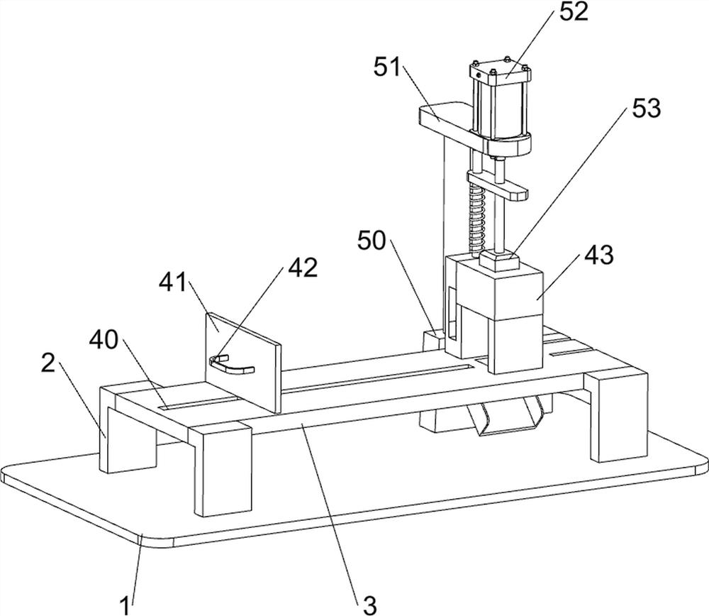
[0026] An adjustable square steel grooving equipment such as figure 1 and figure 2 As shown, it includes a base plate 1, a support 2, a workbench 3, a placement mechanism 4 and a slotting mechanism 5. The base plate 1 is provided with a plurality of supports 2, and a workbench 3 is arranged between the supports 2. On the workbench 3, there are The placement mechanism 4 is provided with a slotting mechanism 5 on the workbench 3 .

[0027] When people need to use this equipment, first people place the square steel on the workbench 3 between the placement mechanism 4, then people adjust the position of the square steel so that the right end of the square steel is tightly positioned under the slotting mechanism 5, and then people can Start the slotting mechanism 5 to make the slotting mechanism 5 operate on the upper and lower sides of the opposite steel for slotting. When the slotting mechanism 5 completes the slotting of the opposite steel and is away from the square steel, pe...

Embodiment 2

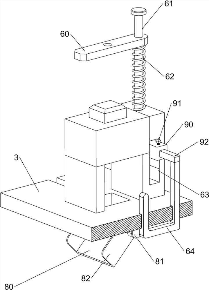
[0032] On the basis of Example 1, such as figure 1 , image 3 , Figure 4 and Figure 5 Shown, also comprise limit mechanism 6, limit mechanism 6 comprises mounting plate 60, connecting rod 61, first spring 62 and limit rod 64, is provided with mounting plate 60 on cylinder 52 expansion rods, is provided with mounting plate 60 Connecting rod 61 is arranged, and connecting rod 61 is slidably connected with N-type block 43, and first spring 62 is sleeved on connecting rod 61, and first spring 62 is connected with N-type block 43 and mounting plate 60, and N-type block 43 is provided with The sliding groove 63 on the right side of the workbench 3 is provided with a limit rod 64 .

[0033] First, people move the limit rod 64 upwards, so that the limit rod 64 limits the position of the square steel, and then when the cylinder 52 telescopic rod moves downward, the cylinder 52 telescopic rod drives the mounting plate 60 and the connecting rod 61 to move downward. A spring 62 was ...


PUM


Abstract

The invention relates to grooving equipment, in particular to adjustable square steel grooving equipment. According to the adjustable square steel grooving equipment, uniform grooving can be achieved, people can conveniently collect waste, and the grooving distance can be adjusted. The adjustable square steel grooving equipment comprises a bottom plate, a workbench, a placing mechanism and a grooving mechanism, wherein the bottom plate is provided with a plurality of supports, the workbench is arranged between the supports, the placing mechanism is arranged on the workbench, and the grooving mechanism is arranged on the workbench. According to the adjustable square steel grooving equipment, the square steel is guided through the placing mechanism, so that the square steel is not easy to deviate during movement, then the square steel is rapidly slotted under the cooperation of the grooving mechanism, and by arranging a limiting mechanism, under the cooperation of the placing mechanism, the position of the square steel is limited, and then uniform grooving of the square steel is achieved.

Description

technical field [0001] The invention relates to a slotting device, in particular to an adjustable square steel slotting device. Background technique [0002] After the square steel is formed, people usually need to process the square steel. Among them, slotting is a relatively common processing method. At present, when people slot the square steel, they usually use the slotting device to slot the square steel. First, people place the square steel under the slotting device, and then people start the slotting device to slot the other side steel. After the slotting at one end of the square steel is completed, people move the square steel to make the slotting device slot the next part of the other side steel. Wherein owing to making manually move square steel, so just easily make the groove distance of going out inconsistent, in addition when slotter is grooved on the other side steel, waste material is scattered everywhere easily, so just is not convenient for people to the col...

Claims


Application Information

Patent Timeline
Patent Type & Authority Applications(China)
IPC IPC(8): B21D17/02B21D43/00B21D43/04B21D37/04B21D43/16
CPCB21D17/02B21D37/04B21D43/003B21D43/04B21D43/16
Inventor 李超华
Owner 李超华
Why Eureka
Try Eureka