
Thread rolling machine capable of machining thread ends with different lengths

A threaded end and thread rolling machine technology, applied in the field of thread rolling machines, can solve the problems of loose bolt fixing, increased production costs, and reduced processing quality

Pending Publication Date: 2021-05-07
福建新峰科技有限公司
View PDF0 Cites 2 Cited by
  • Summary
  • Abstract
  • Description
  • Claims
  • Application Information

AI Technical Summary

Problems solved by technology

[0004] Based on the background technology, existing thread rolling machines can only process bolts with threaded ends of a specific length. If threaded ends with different lengths need to be processed, different equipment needs to be replaced, which increases production costs, and the bolts are not firmly fixed when processing bolts. , which reduces the technical problem of processing quality, the present invention proposes a thread rolling machine capable of processing threaded ends of different lengths

Method used


Image

  • Thread rolling machine capable of machining thread ends with different lengths
  • Thread rolling machine capable of machining thread ends with different lengths
  • Thread rolling machine capable of machining thread ends with different lengths

Examples


Embodiment 1

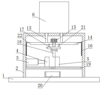
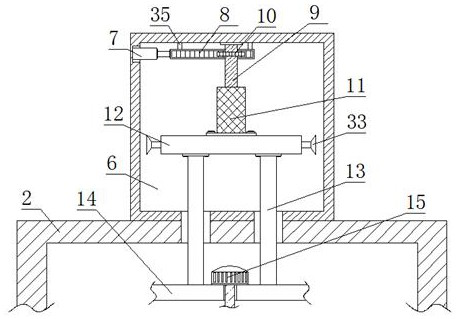
[0024] refer to Figure 1-5In this embodiment, a tooth rubbing machine capable of processing threaded ends of different lengths is proposed, including a base 1, a frame 2 is fixedly connected to the top of the base 1, and an electric push rod 3 is fixedly connected to the inner wall of one side of the frame 2, The frame 2 is fixedly connected with a placement plate 19, the top of the placement plate 19 is fixedly connected with a static tooth plate 5, the top of the placement plate 19 is slidingly connected with a movable tooth plate 4, and one end of the electric push rod 3 is connected to one end of the movable tooth plate 4. The sides are fixedly connected, and the sides where the movable tooth plate 4 and the static tooth plate 5 are close to each other are provided with tooth patterns, and the top of the frame 2 is fixedly connected with a fixed box 6, and a mounting groove is opened on the inner wall of one side of the fixed box 6. One side of the groove is fixedly conne...

Embodiment 2

[0026] In this embodiment, the clamping assembly includes a fixed chamber 23 arranged on the fixed seat 17 , the inner wall of one side of the fixed chamber 23 is rotatably connected with a limit shaft 24 , and one end of the limit shaft 24 extends to one end of the fixed seat 17 . side and is fixedly connected with a handle, and the limit shaft 24 is symmetrically provided with two sections of opposite threads, and the two sections of opposite threads are all threaded with a clamping plate 25, and the sides of the two clamping plates 25 that are close to each other are respectively connected with the processing The two sides of the bolt 18 are closely fitted, and the two clamping plates 25 can be made close to each other by rotating the limit shaft 24, and then the processing bolt 18 can be clamped and fixed, which can prevent the processing bolt 18 from being damaged during processing. The bolt 18 is displaced, which affects the processing quality.

[0027] In this embodimen...


PUM


Abstract

The invention belongs to the field of thread rolling machines, particularly relates to a thread rolling machine capable of machining thread ends with different lengths, and aims at solving the problems that an existing thread rolling machine can only machine bolts with the thread ends with the specific lengths, different devices need to be replaced if the thread ends with the different lengths need to be machined, the production cost is increased, the bolts are not firmly fixed when the bolts are machined, and the machining quality is reduced. According to the scheme, the thread rolling machine comprises a base, the top of the base is fixedly connected with a machine frame, and the inner wall of one side of the machine frame is fixedly connected with an electric push rod. The thread rolling machine is reasonable in structure and convenient to operate, the machined bolts are stably clamped, and therefore it can be prevented that when the machined bolts are machined, the machined bolts move, and the machining quality is influenced; and meanwhile, the distance of the machined bolts between a movable thread plate and a static thread plate is adjustable, so that the threaded ends with the different lengths can be machined, additional equipment is not needed, the production cost is reduced, and use is convenient.

Description

technical field [0001] The invention relates to the technical field of tooth rolling machines, in particular to a tooth rolling machine capable of processing threaded ends of different lengths. Background technique [0002] The thread rolling machine is a kind of processing equipment for the outer surface of cylindrical workpieces. Thread rolling is mostly used for small bolt processing. [0003] Existing thread rolling machines can only process bolts with threaded ends of a specific length. If threaded ends of different lengths need to be processed, different equipment needs to be replaced, which increases production costs, and when processing bolts, the bolts are not firmly fixed, which reduces the processing quality. , so we propose a thread rolling machine that can process threaded ends of different lengths to solve the above-mentioned problems. Contents of the invention [0004] Based on the background technology, existing thread rolling machines can only process bol...

Claims


Application Information

Patent Timeline
IPC IPC(8): B21H3/06
CPCB21H3/06
Inventor 陈小玲
Owner 福建新峰科技有限公司
Learn More