Carton manufacturing device

A technology for making devices and cardboard boxes, applied in paper/cardboard containers, box making operations, packaging, etc., can solve problems such as inability to collect waste materials, and achieve the effects of easy transfer, optimized working environment, and convenient and quick disassembly

Inactive Publication Date: 2021-08-24
邵顺喜
View PDF0 Cites 1 Cited by
  • Summary
  • Abstract
  • Description
  • Claims
  • Application Information

AI Technical Summary

Problems solved by technology

[0009] The object of the present invention is to provide a carton making device to solve the problem that the waste produced by processing cardboard cannot be collected in the above-mentioned background technology

Method used


Image

  • Carton manufacturing device
  • Carton manufacturing device
  • Carton manufacturing device

Examples


Embodiment 1

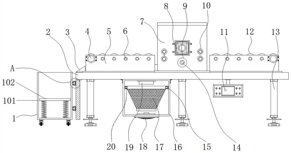
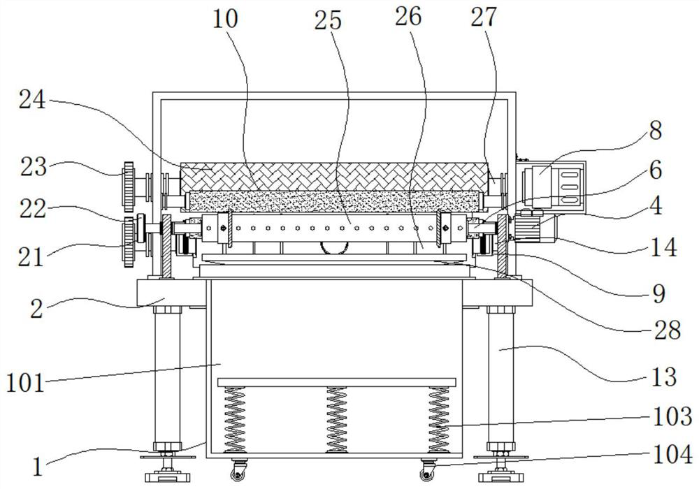
[0035] Example 1: See Figure 1-6 , a kind of cardboard box making device, comprises base plate 2, and support column 13 is evenly fixedly connected with two ends of base plate 2 bottom respectively, and support column 13 is provided with six groups, and one end of base plate 2 is provided with collection structure 1, and the middle position of base plate 2 top A frame body 7 is fixedly connected to the frame body 7, and a second drive motor 8 is fixedly connected to the middle position of one end of the frame body 7. The model of the second drive motor 8 can be Y90S-2, and the middle position between the two ends of the frame body 7 A second drive shaft 27 is movably connected at the top of the bottom plate 2, and one side of the top of the bottom plate 2 is fixedly connected with the material guide plate 3, and the outside of the second drive shaft 27 is fixedly connected with a pressing roller 24, and the bottom between the two ends of the frame body 7 is movable respectivel...

Embodiment 2

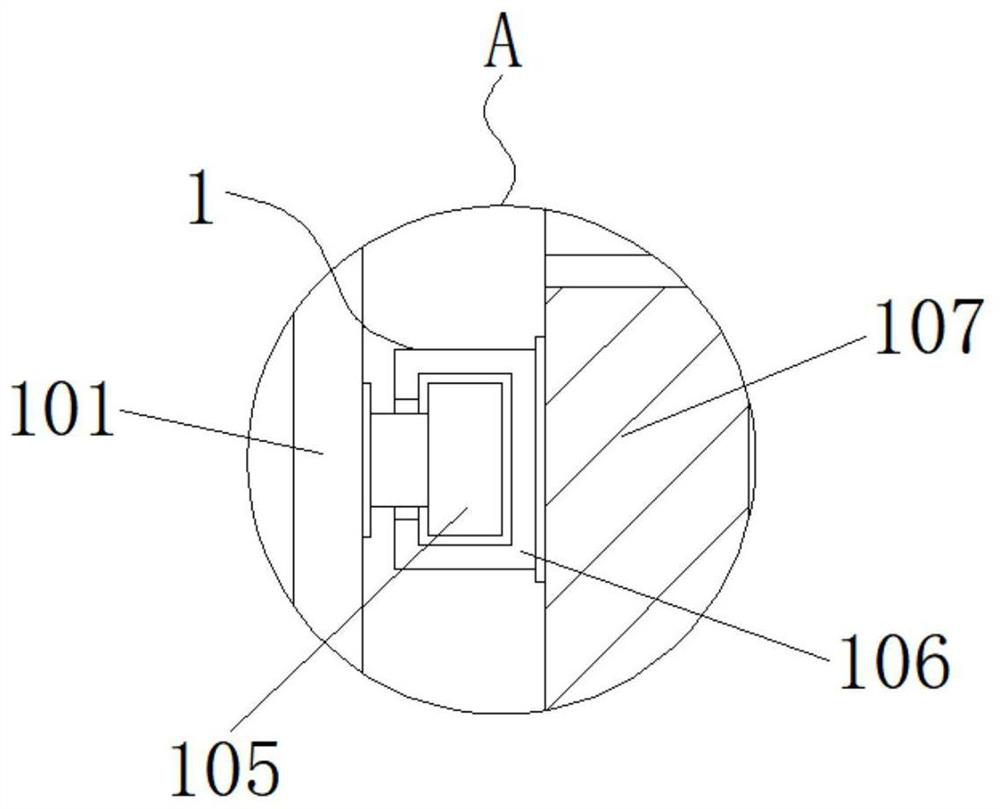
[0039] Embodiment 2: The collection structure 1 is composed of a collection tank 101, a carrier plate 102, a buffer spring 103, a moving wheel 104, a slider 105, a stable chute 106 and a fixed vertical plate 107, and the fixed vertical plate 107 is fixedly connected to the bottom of the bottom plate 2. One side, one side of the fixed vertical plate 107 is provided with a collection tank 101, the four corners of the bottom end of the collection tank 101 are respectively fixedly connected with moving wheels 104, the inside of the collection tank 101 is provided with a carrier plate 102, and the inside bottom of the collection tank 101 The buffer springs 103 are evenly and fixedly connected to both sides, and the tops of the buffer springs 103 are respectively fixedly connected to the bottom of the carrier plate 102, the two ends on one side of the collection tank 101 are fixedly connected to the sliders 105 respectively, and the two ends on the side of the fixed vertical plate 107...

Embodiment 3

[0043] Embodiment 3: The assembly and disassembly structure 9 is composed of an adjustment plate 901, a mounting groove 902, a connecting bolt 903, a connecting hole 904 and a connecting block 905. The mounting grooves 902 are respectively fixedly connected to one end of the connecting shaft 14, and the connecting blocks 905 are respectively fixedly connected to the The two ends of the processing plate roller 26 and the tops of the mounting grooves 902 are respectively movably connected with the adjusting discs 901, the tops of the mounting grooves 902 are respectively plugged with connecting bolts 903, and the inside of the connecting block 905 is respectively provided with connecting holes 904 and connecting bolts 903. The top ends of the connecting pins respectively pass through the interior of the adjusting plate 901, and the bottom ends of the connecting bolts 903 respectively pass through the interior of the connecting hole 904;

[0044] The inside of the adjustment disc ...


PUM


Abstract

The invention discloses a carton manufacturing device, and particularly relates to the technical field of carton machining. The carton manufacturing device comprises a bottom plate, six groups of supporting columns are uniformly and fixedly connected to the two ends of the bottom of the bottom plate, a collecting structure is arranged at one end of the bottom plate, and a frame is fixedly connected to the middle of the top end of the bottom plate. A cleaning mechanism is arranged on the other side of the bottom of the bottom plate, during use, machined paperboard waste is collected through a collection hopper, the waste is conveyed into a box body through a discharging pipe, discharging is assisted through a negative-pressure fan, the waste is prevented from being accumulated in the collection hopper, the paperboard waste is collected through a collection bag arranged in the box body, after the collection bag is full, the collection bag can be conveniently and rapidly detached and cleaned through a clamping structure formed between a clamping block and a clamping groove, the operability is high, the working environment is optimized, and the situation that the paperboard waste is accumulated in the machining position to affect machining operation of cartons is prevented.

Description

technical field [0001] The invention relates to the technical field of cardboard box processing, in particular to a cardboard box manufacturing device. Background technique [0002] Cardboard boxes are widely used packaging products in modern logistics. They not only have the function of containing and protecting products, but also have an important responsibility for aesthetics. With the development of the e-commerce industry, the demand for cardboard boxes is increasing day by day. However, the sales profit of cardboard boxes is generally not high. In order to reduce the cost of cardboard box processing and obtain greater profits, a cardboard box production device reduces labor costs and improves the sales profit of cardboard boxes. However, the existing The carton making device still has some defects in the process of actual use. [0003] In the process of realizing the present invention, the inventors have found that at least the following problems in the prior art have...

Claims


Application Information

Patent Timeline
Patent Type & Authority Applications(China)
IPC IPC(8): B31B50/04B31B50/00B31B50/94
CPCB31B50/006B31B50/042B31B50/94
Inventor 邵顺喜
Owner 邵顺喜
Why Eureka
Try Eureka