Disassembling and assembling method for rounding machining assembly

A disassembly method and component technology, which is applied in metal processing equipment, feeding devices, positioning devices, etc., can solve the problems of inconvenient disassembly and replacement of round processing components, and achieve convenient and fast disassembly and replacement, quality assurance, and convenient and fast installation Effect

Pending Publication Date: 2022-04-15
天津市德通制罐有限公司
View PDF0 Cites 0 Cited by
  • Summary
  • Abstract
  • Description
  • Claims
  • Application Information

AI Technical Summary

Problems solved by technology

[0003] The purpose of the present invention is to provide a method for disassembling and assembling the round processing components, so as to solve the problem that it is inconvenient to disassemble and replace the round processing components in the above-mentioned background technology

Method used


Image

  • Disassembling and assembling method for rounding machining assembly
  • Disassembling and assembling method for rounding machining assembly
  • Disassembling and assembling method for rounding machining assembly

Examples


Embodiment 1

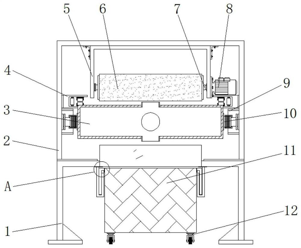
[0020] Example 1: See Figure 1-4 , a method for disassembling and assembling a circle processing assembly, comprising a support frame 1, a frame body 2 is fixedly connected to the top of the support frame 1, and a cylinder 3 is arranged at the bottom of the front end between the two sides inside the frame body 2, and the frame body 2 The middle position of the rear end between the two sides of the interior is fixedly connected with the fixing groove 4, the bottom of the front end between the two sides of the frame body 2 is fixedly connected with the sleeve 9, and the front end at the middle position of the bottom of the support frame 1 is provided with a collecting tank 11. The middle positions on both sides of the forming cylinder 3 are respectively fixedly connected with the connecting block 10, the front end at the middle position of the inner top of the frame body 2 is fixedly connected with the tank body 5, and the bottom end of one side of the tank body 5 is fixedly con...

Embodiment 2

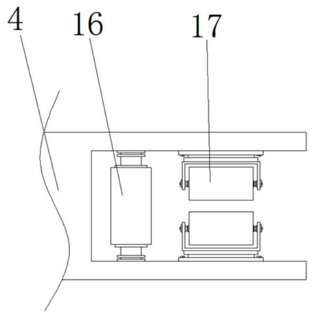
[0023] Embodiment 2: The fixed side between the two ends inside the fixed groove 4 is respectively movably connected with a limiting column 16, and one side of the two ends inside the fixed groove 4 is respectively fixedly connected with a stable guide wheel 17;

[0024] Specifically, such as figure 1 and image 3 As shown, in use, the tinplate in the process of being transferred into a circle is limited by the limiting column 16 that is movably connected between the two ends of the fixed groove 4, and is fixedly connected to the stable ends of the fixed groove 4 on one side. The guide wheel 17 conveys and guides the tinplate, thereby achieving the purpose of stabilizing the tinplate in the rounding process, thereby ensuring the quality of the tinplate in the rounding process.

Embodiment 3

[0025] Embodiment 3: The middle position of the front end of the support frame 1 is fixedly connected with a material guide plate 20, the four corners of the bottom end of the collection tank 11 are respectively fixedly connected with moving wheels 12, and the front ends on both sides of the inner top of the support frame 1 are respectively fixedly connected with Stable slots 19, the tops on both sides of the collection tank 11 are respectively fixedly connected with installation boards 18, the installation boards 18 are respectively in the shape of "L", and the installation boards 18 are respectively inserted in the inside of the stable slots 19;

[0026] Specifically, such as figure 1 and Figure 4 As shown, when in use, the mounting plate 18 fixedly connected to the top of both sides of the collecting tank 11 is plugged into the inside of the stabilizing slot 19 fixedly connected to the front ends of both sides of the inner top of the support frame 1, thereby achieving the ...


PUM


Abstract

The invention discloses a method for disassembling and assembling a rounding processing assembly, which comprises a support frame, the top end of the support frame is fixedly connected with a frame body, a rounding cylinder is arranged at the bottom of the front end between two sides in the frame body, and fixing grooves are fixedly connected to the middle positions of the rear end between two sides in the frame body respectively. According to the disassembling and assembling method of the pair of circle forming machining assemblies, connecting blocks are fixedly connected to the middle positions of the two sides of a circle forming cylinder correspondingly, and the circle forming cylinder is placed between connecting shafts arranged in a sleeve when the circle forming machining assembly is used; then connecting sleeve grooves sleeving the connecting shafts are fixed to the outer portions of connecting blocks fixedly connected to the middle positions of the two sides of the formed cylinder, and the connecting sleeve grooves are limited to the outer portions of the connecting shafts through limiting blocks, so that the purpose of fixing the formed cylinder between the connecting shafts is achieved; and therefore, the effect of conveniently and quickly mounting, dismounting and replacing the circle forming cylinder is achieved, and the problem that the circle forming machining assembly is inconvenient to dismount, mount and replace is solved.

Description

technical field [0001] The invention relates to the field of tinplate rounding technology, in particular to a disassembly method for rounding processing components. Background technique [0002] Tinplate is tin-plated iron. Packaging containers made of tinplate are widely used in food packaging, pharmaceutical packaging, daily necessities packaging, In terms of instrumentation packaging, industrial product packaging, etc., when tinplate is processed into packaging containers, it is necessary to use a tinplate rounding device to round the tinplate. However, in the actual use of the tinplate rounding device, it is still inconvenient to disassemble and replace the rounding processing components; the tinplate in the rounding process cannot be guided stably, and it is inconvenient to collect and transfer the tinplate at the rounding processing place. . For this reason, we propose a method of disassembling and assembling the components processed in circles to solve these problem...

Claims


Application Information

Patent Timeline
Patent Type & Authority Applications(China)
IPC IPC(8): B21D5/14B21D43/20
Inventor 芦东利
Owner 天津市德通制罐有限公司
Why Eureka
Try Eureka