Punching equipment for connector

A technology of punching equipment and connectors, applied in drilling/drilling equipment, metal processing equipment, boring/drilling and other directions, can solve problems such as affecting punching efficiency, multi-manpower and time, and reduce operational troubles , The effect of preventing damage and reducing the trouble of collection

Active Publication Date: 2021-05-07
赣州市硕祺电子科技有限公司
View PDF7 Cites 1 Cited by
  • Summary
  • Abstract
  • Description
  • Claims
  • Application Information

AI Technical Summary

Problems solved by technology

[0005] In order to overcome the shortcomings of the general punching machine that consumes more manpower and time, and needs to manually clean up the debris, thereby affecting the efficiency of punching, the technical problem to be solved by the present invention is: to provide a punching machine with high punching efficiency. And punching equipment for connectors that can automatically clean debris

Method used


Image

  • Punching equipment for connector
  • Punching equipment for connector
  • Punching equipment for connector

Examples


Embodiment 1

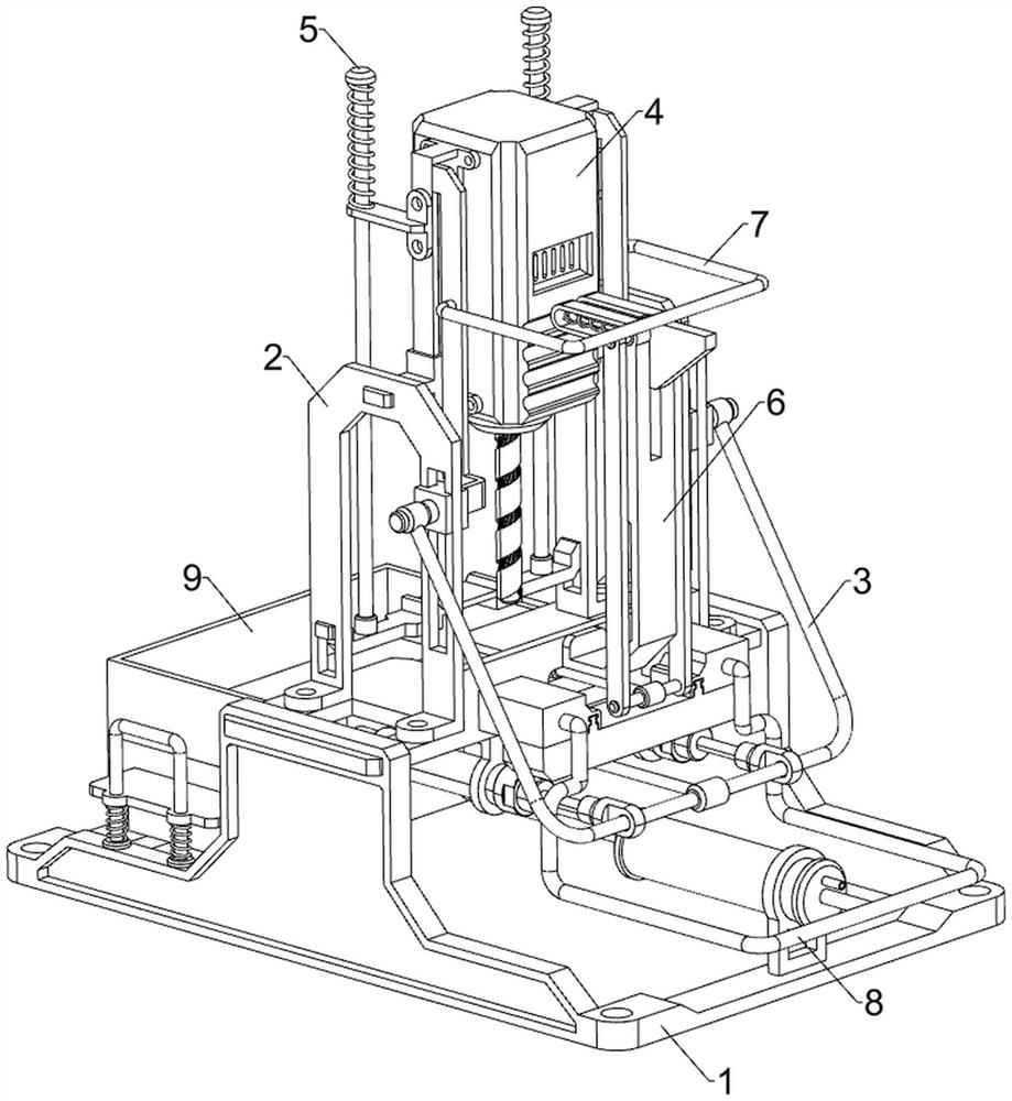
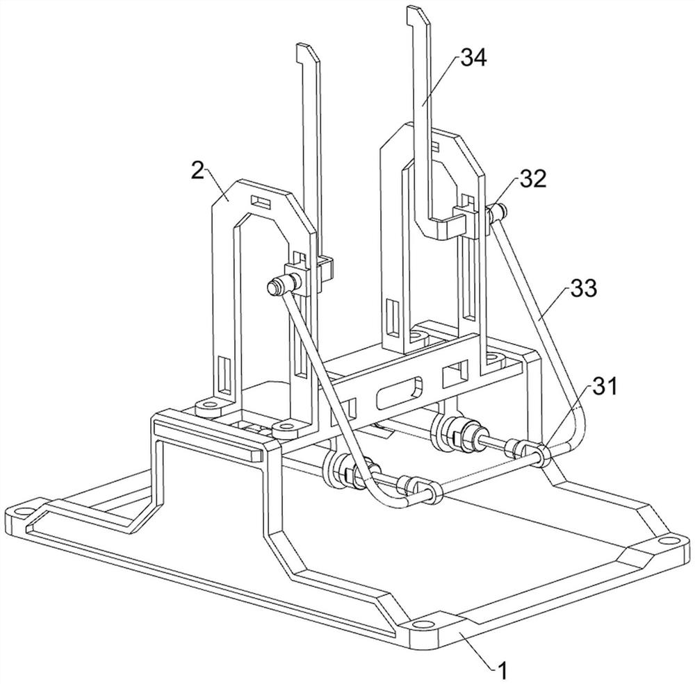
[0030] A punching device for connectors such as Figure 1 to Figure 3 As shown, it includes a bracket 1, a support plate 2, a drive assembly 3 and a drilling assembly 4. The support plate 2 is fixed on the front and rear sides of the upper part of the support 1 through bolts, and the drive assembly is arranged between the support plate 2 and the bracket 1. 3. A drilling assembly 4 is provided between the support plates 2 .

[0031] When the connector needs to be drilled, the connector is placed on the bracket 1, and then the driving component 3 is started, the driving component 3 will drive the drilling component 4 to operate, and then the drilling component 4 will punch the connector , when the connector punching is completed, control the driving assembly 3 to operate in reverse, so that the drilling assembly 4 operates in reverse and resets, and then replace another connector on the bracket 1, and then repeat the above operation, when all the connectors are all After the pu...

Embodiment 2

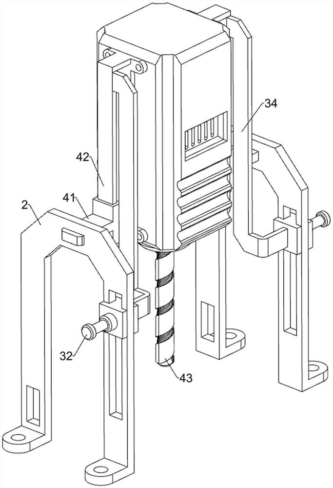
[0037] On the basis of Example 1, such as figure 1 , Figure 4 , Figure 5 , Image 6 , Figure 7 with Figure 8 As shown, it also includes a pressing assembly 5, and the pressing assembly 5 includes a guide plate 51, a vertical bar 52, a first spring 53 and a pressing plate 54, and the slide rail 42 is fixed with a guide plate 51 by bolts, and the guide plate 51 A vertical rod 52 is slidably connected to the top, a first spring 53 is connected between the vertical rod 52 and the guide plate 51 , and a pressing plate 54 is welded between the lower sides of the vertical rod 52 .

[0038] When the slide rail 42 moves downward, it will drive the guide plate 51, the vertical bar 52, the first spring 53 and the pressing plate 54 to move downward together. When the pressing plate 54 moves to contact with the bracket 1 and the connector, the pressing plate 54 and the vertical bar 52 No longer moving down, the guide plate 51 will continue to move down, and then the first spring 5...


PUM


Abstract

The invention relates to punching equipment, in particular to punching equipment for a connector. The technical problem to be solved by the invention is to provide punching equipment for a connector. The punching equipment is high in punching efficiency and capable of automatically cleaning chippings. The punching equipment for the connector comprises a bracket, supporting plates mounted at two sides of the bracket, a driving assembly mounted between the supporting plates and the bracket, and a drilling assembly installed between the supporting plates. The punching equipment is provided with a pressing assembly, so that the situation that the connector moves when the connector is punched, and the punching effect is affected can be prevented; and the punching equipment is provided with a push-out assembly, so that a push plate can push out the punched connector, a worker can conveniently take out the punched connector, and the working efficiency of the worker is improved.

Description

technical field [0001] The invention relates to a punching device, in particular to a punching device for a connector. Background technique [0002] Connectors are also called joints and sockets in China, and generally refer to electrical connectors, that is, devices that connect two active devices to transmit current or signals. [0003] Generally, the connector needs to be punched. The general punching machine requires the staff to place the connector on the punching machine, and then control the punching machine to punch the connector. After punching, the staff needs to take out the connector. , so it takes a lot of manpower and time, and more debris will be generated when drilling, which needs to be cleaned manually, which will affect the efficiency of drilling. [0004] Therefore, it is necessary to design a punching device for connectors that has high punching efficiency and can automatically clean debris. Contents of the invention [0005] In order to overcome the...

Claims


Application Information

Patent Timeline
Patent Type & Authority Applications(China)
IPC IPC(8): B23B41/00B23Q11/00
CPCB23B41/00B23Q11/0042
Inventor 谢红军谢玮琦谢玮浩
Owner 赣州市硕祺电子科技有限公司
Why Eureka
Try Eureka