
A new multifunctional drilling machine

A multi-functional, drilling machine technology, applied in the field of machinery, can solve the problems of time-consuming, laborious, troublesome, and single function.

Active Publication Date: 2021-03-19
人民非物质文化传播有限公司
View PDF5 Cites 0 Cited by
  • Summary
  • Abstract
  • Description
  • Claims
  • Application Information

AI Technical Summary

Problems solved by technology

The existing drilling machine has a single function, and it is inconvenient for the drilling machine to drill holes on the flat plate to drill holes in the round tube. It needs to replace the equipment, which is time-consuming and laborious, which is very troublesome and delays the working time, and it is very inconvenient to fix the round tube. Adjust the drilling angle of the round pipe, so it is necessary to design a new type of drilling machine to improve work efficiency

Method used


Image

  • A new multifunctional drilling machine
  • A new multifunctional drilling machine
  • A new multifunctional drilling machine

Examples


Embodiment Construction

[0023] Below in conjunction with accompanying drawing and specific embodiment the present invention is described in further detail:

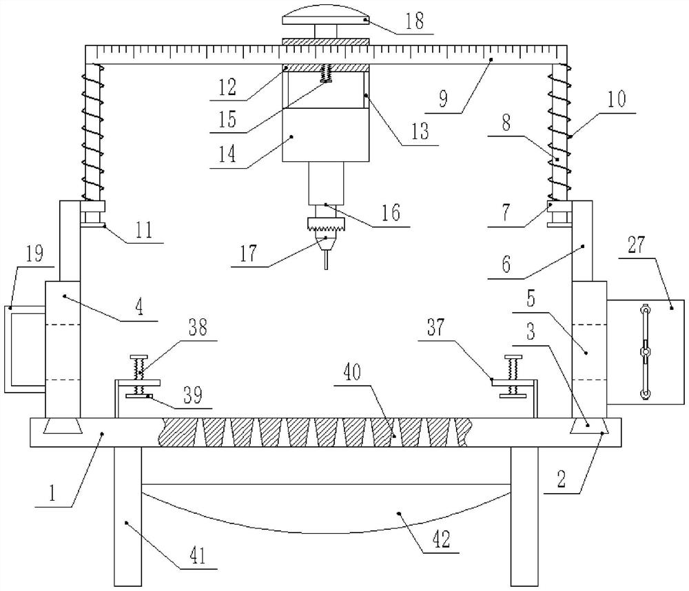
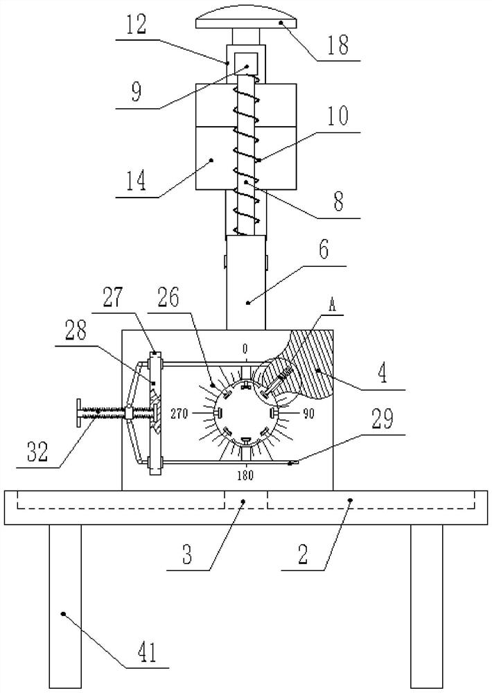
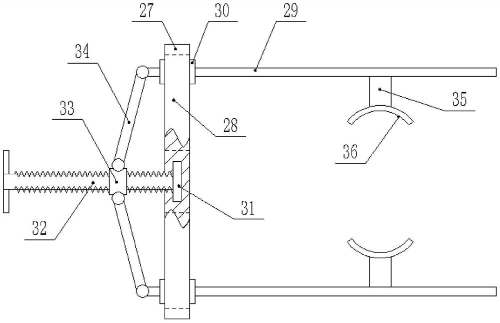
[0024] Such as figure 1 , figure 2 , image 3 , Figure 4 As shown, a new multifunctional drilling machine comprises a horizontal plate 1, the two sides of the top surface of the horizontal plate 1 are provided with trapezoidal grooves 2 parallel to each other, and the trapezoidal groove 2 is provided with a slide block 3 slidingly connected thereto. The section of 3 is trapezoidal and fits with the inner wall of the trapezoidal groove 2, and the top surface of the slider 3 is vertically fixed with a riser 4, and the middle of the riser 4 is provided with a through hole 5 corresponding to each other, and the top surface of the through hole 5 A vertical bar 6 is vertically fixed, and a limit sleeve 7 is fixed at the side end of the vertical bar 6, and a slide bar 8 slidingly connected with it is vertically inserted in the limit sleeve 7, and ...


PUM


Abstract

The invention discloses a novel multifunctional drilling machine. The novel multifunctional drilling machine comprises a transverse plate. The two sides of the top face of the transverse plate are provided with parallel trapezoid-shaped grooves. The trapezoid-shaped grooves are internally provided with sliding blocks which are in sliding connection with the trapezoid-shaped grooves. The cross sections of the sliding blocks are trapezoid and are attached to the inner walls of the corresponding trapezoid-shaped grooves. The top faces of the sliding blocks are vertically and fixedly provided withvertical plates. The middles of the vertical plates are provided with corresponding through holes. The top faces of the through holes are vertically and fixedly provided with vertical rods. The sideends of the vertical rods are fixedly provided with limiting sleeves. Sliding rods in sliding connection with the limiting sleeves are vertically inserted into the corresponding limiting sleeves. A cross bar is fixed between the tops of the sliding rods. Springs which are connected to the outer walls of the sliding rods in a sleeving manner are arranged between the cross bar and the limiting sleeves. The bottoms of the sliding rods are fixedly provided with baffle rings. The cross bar is sleeved with a sliding sleeve which is in sliding connection with the cross bar. The lower end of the sliding sleeve is vertically and fixedly provided with a fixing frame. Punching positions are conveniently adjusted by adjusting the transverse positions and the longitudinal positions of a drill bit, operation is easy and convenient, flexibility is high, the drilling machine can be universal to punch a round pipe and a transverse plate, functions are diversified, time and labor are saved, and the working efficiency is improved.

Description

technical field [0001] The invention relates to the mechanical field, in particular to a novel multifunctional drilling machine. Background technique [0002] Drilling machine refers to a machine tool that mainly uses a drill bit to process holes in a workpiece. Generally, the rotation of the drill bit is the main movement, and the axial movement of the drill bit is the feed movement. The drilling machine has a simple structure and relatively low machining accuracy. It can drill through holes and blind holes, replace special tools, expand, countersink, ream or tap. During the machining process, the workpiece does not move, let the tool move, align the center of the tool with the center of the hole, and make the tool rotate (main movement). The characteristic of the drilling machine is that the workpiece is fixed and the tool rotates. The existing drilling machine has a single function, and it is inconvenient for the drilling machine to drill holes on the flat plate to dri...

Claims


Application Information

Patent Timeline
Patent Type & Authority Patents(China)
IPC IPC(8): B23Q1/44B23Q3/06B23Q11/00B23Q17/00
CPCB23Q1/44B23Q3/06B23Q3/064B23Q11/0042B23Q17/003
Inventor 张明明
Owner 人民非物质文化传播有限公司
Learn More