Multifunctional punching device for motor production and machining

A punching device and multi-functional technology, applied in electromechanical devices, positioning devices, metal processing equipment, etc., can solve the problems of inability to quickly detect motor casings, improve the difficulty of operation by staff, and inability to quickly eliminate defective products, and achieve protection. The effect is good, the operation difficulty is reduced, and the processing accuracy is high.

Pending Publication Date: 2022-03-18
温亮亮
View PDF0 Cites 0 Cited by
  • Summary
  • Abstract
  • Description
  • Claims
  • Application Information

AI Technical Summary

Problems solved by technology

[0003] During the production process of the motor casing, it is necessary to punch holes in the motor casing. A large amount of dust will be generated when punching holes, and the dust will accumulate in the punched parts, which will affect the punching effect. However, the existing dust-proof mechanism can only be simple. To deal with the dust, it is not possible to cool down the perforated part at the same time as the dust is processed. When the motor shell is drilled, the drilled part will generate high temperature, which will cause damage to the motor shell, and the existing dust-proof and other auxiliary The mechanism needs to add an additional driving device, which not only greatly increases the difficulty of the operation of the staff, but also has higher processing costs; the existing punching device does not have a measuring mechanism, and cannot quickly detect the machined motor casing, and thus cannot detect the remaining parts. Defective products are quickly eliminated, thereby reducing processing efficiency

Method used


Image

  • Multifunctional punching device for motor production and machining
  • Multifunctional punching device for motor production and machining
  • Multifunctional punching device for motor production and machining

Examples


Embodiment 1

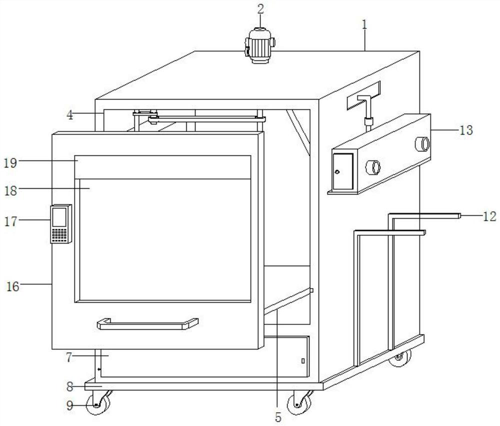
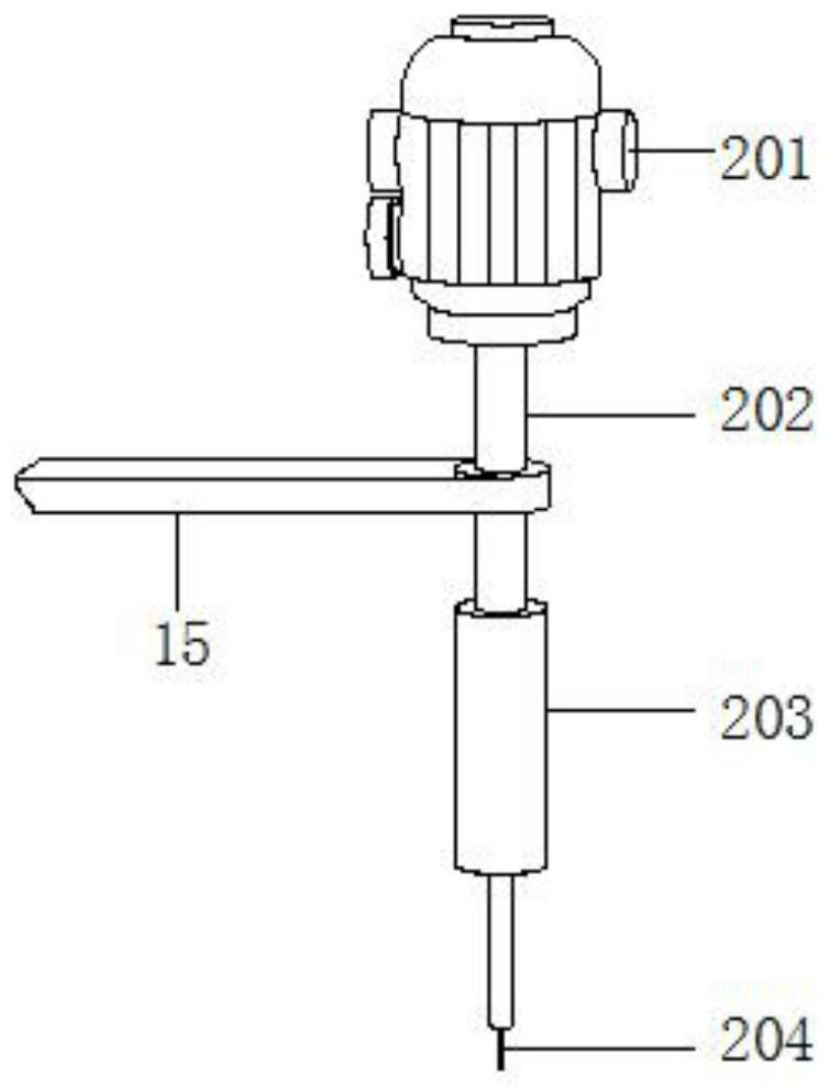
[0046] refer to figure 1 , 2 , 3, 11, 12, a multifunctional punching device for motor production and processing, including a device shell 1, an operation port 4 is provided at the front end of the device shell 1, a punching assembly 2 is fixedly installed in the middle of the upper end of the device shell 1, and the punching The lower end of the hole assembly 2 runs through the device casing 1 and extends to the inside of the device casing 1. The installation platform 5 is slidably installed on the inner wall of the device casing 1 through the slide rail. 16 is arranged at the operation port 4, and the front end of the door panel 16 is fixedly equipped with a transparent observation window 18, a display screen 19 and a control panel 17, and the display screen 19 is located above the transparent observation window 18, and the control panel 17 is located on the left side of the transparent observation window 18. The lower end of the table 5 is fixed with a measuring mechanism 1...

Embodiment 2

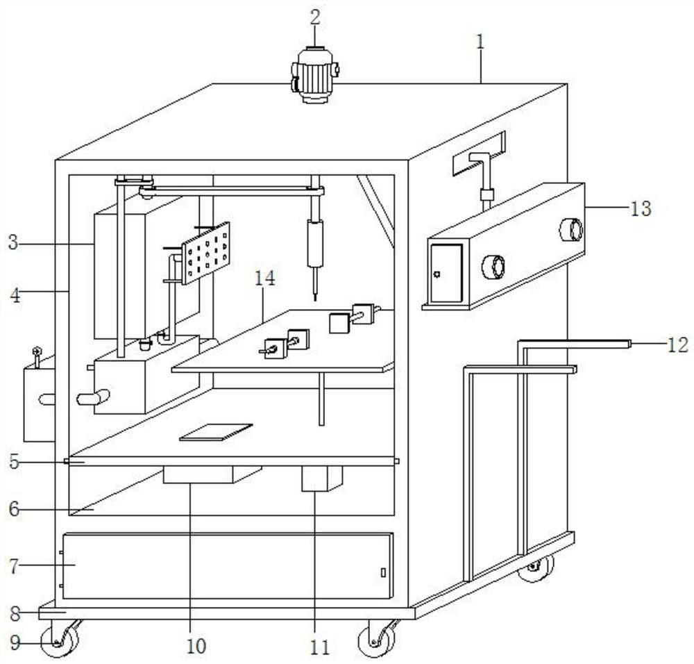
[0052] refer to Figure 4-7 , a multifunctional punching device for motor production and processing. Compared with Embodiment 1, this embodiment also includes an auxiliary punching mechanism 3, and the auxiliary punching mechanism 3 includes a first mounting shell 301, a second mounting shell 309 and a third mounting shell. The installation shell 312, the first installation shell 301 and the second installation shell 309 are fixedly installed on the left end surface inside the device shell 1, and are all located above the installation platform 5, the first installation shell 301 is located above the second installation shell 309, and the third installation shell 312 is fixedly installed on the left end surface of the device casing 1, and the middle part of the upper end of the first installation casing 301 is movable through a connecting shaft 304. The connecting shaft 304 is arranged along the vertical direction, and the lower end of the connecting shaft 304 extends to the ins...

Embodiment 3

[0058] refer to Figure 8-9 , a multifunctional punching device for motor production and processing. Compared with Embodiment 1, this embodiment also includes a measuring mechanism 10. The measuring mechanism 10 includes a fixed shell 1001. The fixed shell 1001 is fixedly installed on the lower end of the mounting table 5. The fixed shell 1001 A pressure sensor 1004 is fixedly installed at the inner bottom, and a pressure guide bump 1002 is attached to the sensing end of the pressure sensor 1004. The upper end of the pressure guide bump 1002 runs through the fixed shell 1001, and a measuring board 1003 is installed on the upper end of the measuring board 1003. The activity runs through the installation platform 5 and extends above the installation platform 5;

[0059] The pressure guiding protrusion 1002 is slidably attached to the inner wall of the fixed shell 1001 along the vertical direction.

[0060] Working principle: The motor casing after punching can be put on the mea...


PUM


Abstract

The invention relates to the technical field of motor production and processing, and discloses a multifunctional punching device for motor production and processing, which comprises a device shell, the front end of the device shell is provided with an operation port, the middle position of the upper end of the device shell is fixedly provided with a punching assembly, and the lower end of the punching assembly penetrates through the device shell. An operation opening is formed in the device shell and extends into the device shell, a mounting table is slidably mounted on the inner wall of the device shell through a sliding rail, the front end of the mounting table penetrates through the operation opening and is fixedly provided with a door plate, the door plate is arranged at the operation opening, and a transparent observation window, a display screen and a control panel are fixedly mounted at the front end of the door plate; the display screen is located above the transparent observation window, the control panel is located on the left side of the transparent observation window, and a measuring mechanism and an adjusting air cylinder are fixedly mounted at the lower end of the mounting table. The device is high in machining precision, high in efficiency, high in automation degree, simpler and more convenient to operate, good in protection effect, convenient to move and diversified in function.

Description

technical field [0001] The invention relates to the technical field of motor production, in particular to a multifunctional punching device for motor production and processing. Background technique [0002] A motor is an electromagnetic device that converts or transmits electrical energy according to the law of electromagnetic induction. The motor is represented by the letter M (the old standard is D) in the circuit. Its main function is to generate driving torque as a power source for electrical appliances or various machines. The generator is represented by the letter G in the circuit. Its main function The function is to convert mechanical energy into electrical energy. [0003] During the production process of the motor casing, it is necessary to punch holes in the motor casing. A large amount of dust will be generated when punching holes, and the dust will accumulate in the punched parts, which will affect the punching effect. However, the existing dust-proof mechanism...

Claims


Application Information

Patent Timeline
Patent Type & Authority Applications(China)
IPC IPC(8): B23B41/00B23Q3/06B23Q11/00B23Q11/10B23Q17/20H02K15/14
CPCB23B41/00B23Q3/062B23Q17/20B23Q11/10B23Q11/005B23Q11/0046H02K15/14
Inventor 温亮亮
Owner 温亮亮
Why Eureka
Try Eureka